/
−−−−−<SET MODE>−−−−−−
・UNIT
g/l
・UNDER ALARM POINT
+8.50000 E+2
・OVER ALARM POINT
+1.15000 E+3
・μ1
+8.00000 E+2
↓−−−−<SUB MENU>−−−−−
MAIN| | |
MENU| | |ENTR
E-880TM-3-E
13
(1)Viscosity (μ) submenu screen
At the submenu, move the cursor to the desired setup item with the up and down arrow keys.
At the touch of function key “ENTR”, the screen switches to the desired item setup screen.
① Viscosity comp. (μ) - unit setup (UNIT) p. 135
② Viscosity comp. (μ) - under alarm point (UNDER ALARM POINT) p. 135
③ Viscosity comp. (μ) - over alarm point (OVER ALARM POINT) p. 136
④ Viscosity comp. (μ) - viscosities μ1 setup (μ1) p. 136
To the setup screen pointed by the cursor
SET mode main menu screen ⇒ 6.2 SET mode main menu screen p. 36
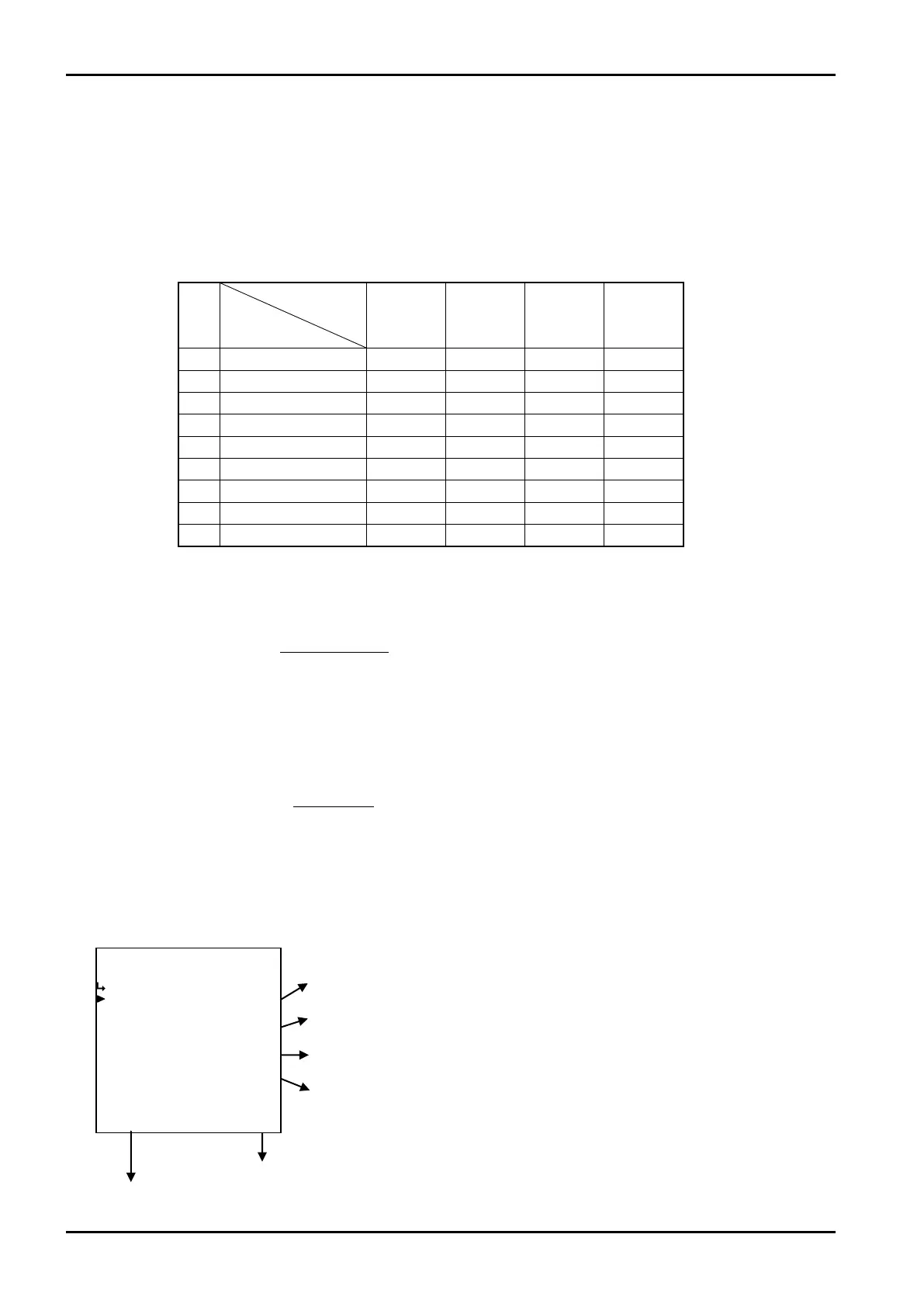
6.4.26 Viscosity compensation (μ) setup (VISCOSITY COMP. (μ))
To determine error correction coefficients associated with fluid velocity and viscosity, parameters -
measurement units, under alarm point, over alarm point, viscosities 1 to 3, flowrate (frequencies) 1 to 9,
and meter errors 11 to 93 are set here.
※ These settings are used in Models EL4501 and EL4511.
Viscosity data: 3 points Fluid velocity data: 9 points max. Meter error data: 9×3 points max.
No.
μ 1 μ2 μ3 μ
1 Q 1 E 11 E 12 E 13 E 1S
2 Q 2 E 21 E 22 E 23 E 2S
3 Q 3 E 31 E 32 E 33 E 3S
4 Q 4 E 41 E 42 E 43 E 4S
5 Q 5 E 51 E 52 E 53 E 5S
6 Q 6 E 61 E 62 E 63 E 6S
7 Q 7 E 71 E 72 E 73 E 7S
8 Q 8 E 81 E 82 E 83 E 8S
9 Q 9 E 91 E 92 E 93 E 9S
From the viscosity set,E
1S
to E
9S
are determined.
On conditions that μ
1
≦ Viscosity set μ
S
≦μ
2
μ
2
×(μ
S
-μ
1
)
μ
S
×(μ
2
-μ
1
)
E
1S
=E
11
+(E
12
-E
11
)×
Similarly, proceed to work from E
2S
to E
9S
. Also, on conditionsμ
2
≦μ
S
≦μ
3
, determine in the same
way.
Next, determine Q
1
to Q
9
from Q
S
; find Q
n
which is closest to Q
S
from E
1S
to E
9S
, and Q
n+1
, E
nS
, and E
nS+1
,
and calculate the following formula:
(Q
S
-Q
n
)
(Q
n+1
-Q
n
)
E
1
=E
nS
+(E
(n+1)S
-E
nS
)×
Viscosity
Flowrate
(frequencies)(Hz)
設定された粘度値からE
1S
to E
9S
を求めます。
μ
1
≦設定粘度μ
S
≦μ
2
の場合