20%
0% 100%
80%
−5% 105%
Fullscale
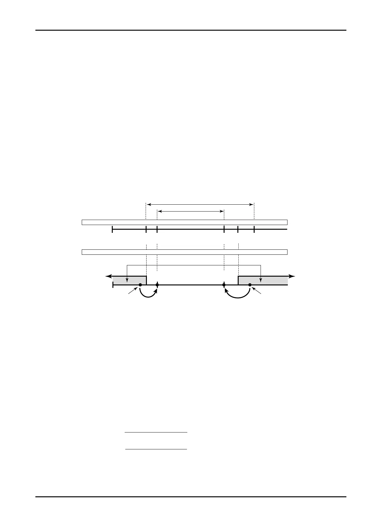
ExampleMeasurementunits(UNIT):%
Baseline(BASESCALE):0%
Fullscale(FULLSCALE):100%
Underalarmpoint(UNDERALARMPOINT):−1%
Overalarmpoint(OVERALARMPOINT):101%
Underfallbacklevel(UNDERFALLBACK):0%
Overfallbacklevel(OVERFALLBACK):100%
Base
Underfallback Overfallback
Underalarmpt. Overalarmpt.
Meas.range
Max. full scale
Full
scale
Min. baseline
Base – full scale setting range
Meas. range
Base
line
Under
alarm pt.
Over fallback
level
Under
fallback level
Over
alarm pt.
Alarm output
Blend input
1% 0% 100% 101%
3.5mA0mA 4mA 20mA 22mA
Flowrate signal meas.Flowrate signal meas.
E-880TM-3-E
1
Alarm point and fallback setup range is determined as follows:
(i)Low limit Base scale -
Full scale - Baseline
×0.5
(ii )High limit Full scale +
Full scale - Baseline
×2
6.4.3 Blend Input Setup (BLEND INPUT)
As the factors associated with blend input, the measurement units, constants (with the input type set to
NONE in the SYS mode), baseline, full scale value, under alarm point, over alarm point, under fallback
level, and over fallback level are established here.
※ These settings are used only in Model EL4401. They are not shown in other models.
① 4 to 20mA and 1 to 5V input type
When the “4 to 20mA” or “I to 5V” is your selection in the input type (SYS mode), respective parameters
are defined as follows:
With 4 to 20mA or 1 to 5V input, the baseline-to-full-scale setting range varies with the given model
(calculation). Set the baseline and full scale setpoint within the range acceptable by the specific model
used. (Failure to set them within this range will nullify assurance for proper operation. ) The base scale
and full scale are referenced when the pulse output scaling is determined. Settings should be determined
carefully taking into consideration the process of calculation, the value of standard span and other
contributing factors.
Temperatures in the RUN mode are indicated relative to the input within the range where the over alarm
point and the under alarm point determine its high and low limit, respectively. If an input goes out of this
range, the output will automatically be clamped at the over fallback or under fallback value.
16
16