Chapter 8: Audio Module, Rev 1.1
8.4.7 Microphone test
A microphone test can be manually performed within the VDR record application by a technician:
1. Ensure the VDR_Record application is not recording;
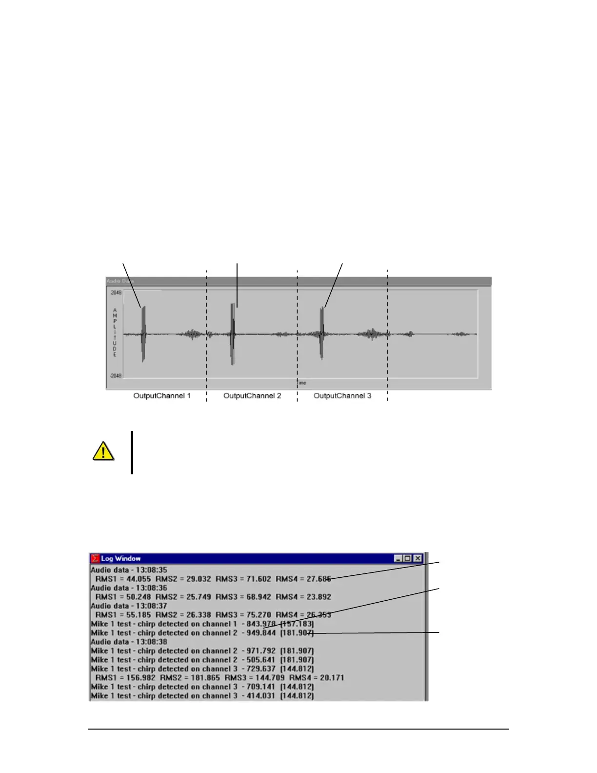
2. Perform the test by starting an Audio Test. which creates an audio histogram in the
audio data window (see figure below);
NOTE: The audio histogram is divided into equal sections. The number of sections
depends on the NumOutPutChannels field set in the <vdrparams.ini> file. Each section
represents 1 second of audio for each OutPutChannel field. An audio “spike” may be
observed in each Audio Output section if a buzzer chirp is detected on that channel (See
Figure 8-28 - Channel 1, Mic 1 Test.)
Buzzer 1 Chirp Buzzer 1 Chirp Buzzer 1 Chirp
Figure 8-28 - Channel 1, Mic 1 Test
Note! The audio spikes shown in the audio histogram are related to the audio
module channels after they have been software mixed via the OutPutChannel
fields of the INI file (output audio). Spikes may exceed top and bottom of histogram
screen.
3. Activate a microphone test by selecting Test Mic X from the Audio A/D menu
4. Review the test results in the Log Window as illustrated in Figure 8-29 -
Microphone Test Results.
RMS Value (for entire
1 sec.)
RMS Sub-Interval Value
(for buzzer)
RMS Microphone test
Value (for entire 1
sec. test)
VDR-100G3/G3S Installation Manual 06/10/2008
8-32