Chapter 11: Operation and Alarm Unit Test and User Guide, Rev. 1.1
11.3 Connecting the OAU
The OAU connects via 2 cable entry glands. To connect the OAU use:
A three-pair cable for the DPU connection; and
A one-pair cable to send the OAU alarm signal to the bridge alarm panel.
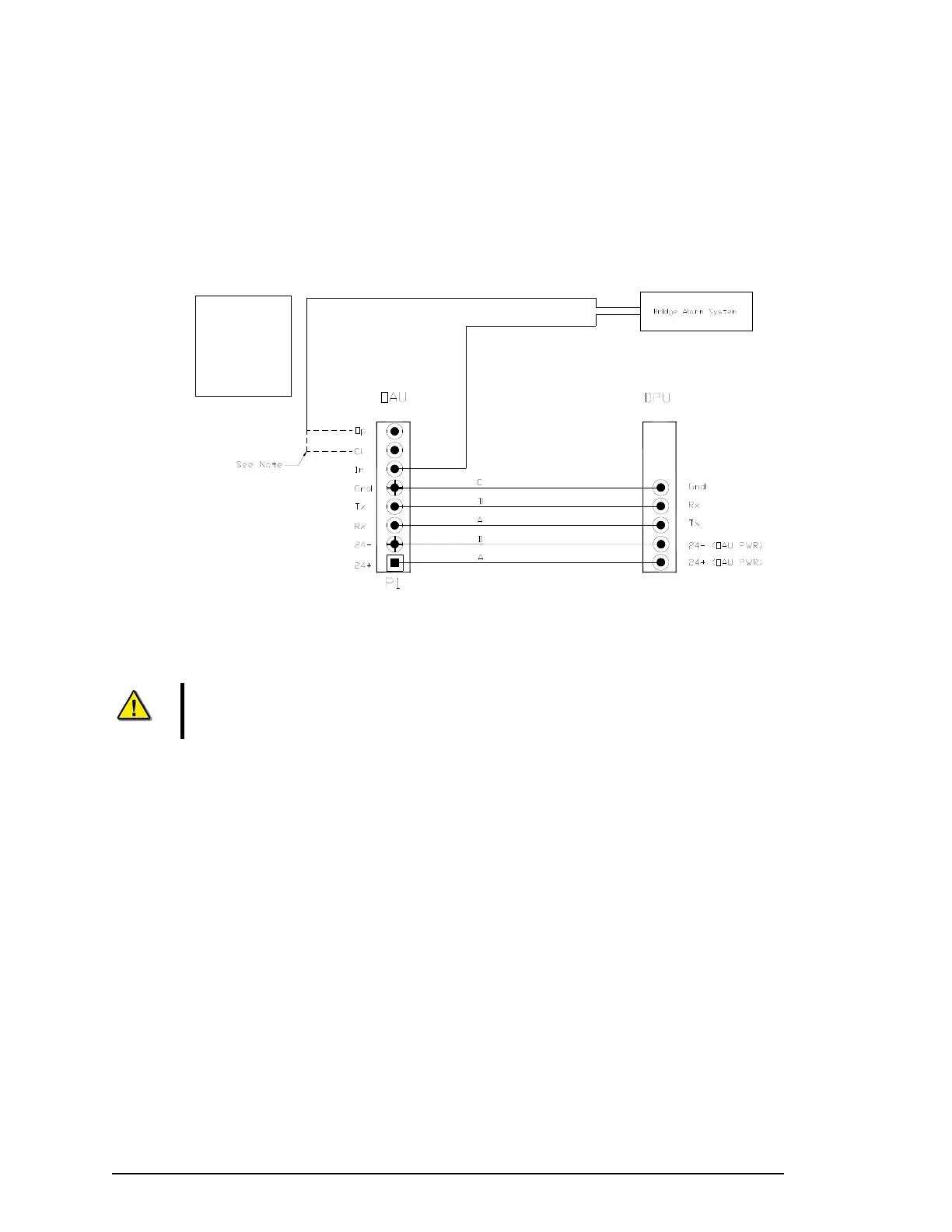
Note:
The Normally Open and Normally Closed connection points are dry contacts. The connection to the Bridge Alarm System will be dependant upon the
requirements of a particular system. The dashed lines indicate possible connections.
OAU Terminal Block Legend:
Op = Normally Open
Cl = Normally Closed
In = Common
Gnd = Ground
Tx = Transmit
Rx = Receive
Figure 11-4 - OAU to DPU Terminal Block Connections.
Note! Communications between the DPU and OAU are via a crossover connection.
11.4 Configuring the OAU
The functionality of these features shall be verified during installation.
1. The VDR_Record application should be loaded and in the record mode;
2. Verify that the OAU indicates “Recording”;
3. Cut the power to the VDR by opening the ship’s dedicated VDR circuit breaker;
4. Observe a “Power Failure” message is reported on the LCD and audible alarm is sounded;
5. Push the ‘Mute’ button to silence the audible alarm;
6. Initiate a securing of data in the DMM internal drive by pressing the “Emergency Backup” button
on the OAU (see Section 11.8 - Error! Reference source not found.):
7. Observe that the OAU indicates “Download Complete” immediately after pressing “Enter” to
initiate the process;
8. Restore the ship’s power to the VDR; and
9. Observe the “Power Failure” message is cleared on the OAU.
VDR-100G3/G3S Installation Manual 06/10/2008
5