Chapter 8: Audio Module, Rev 1.1
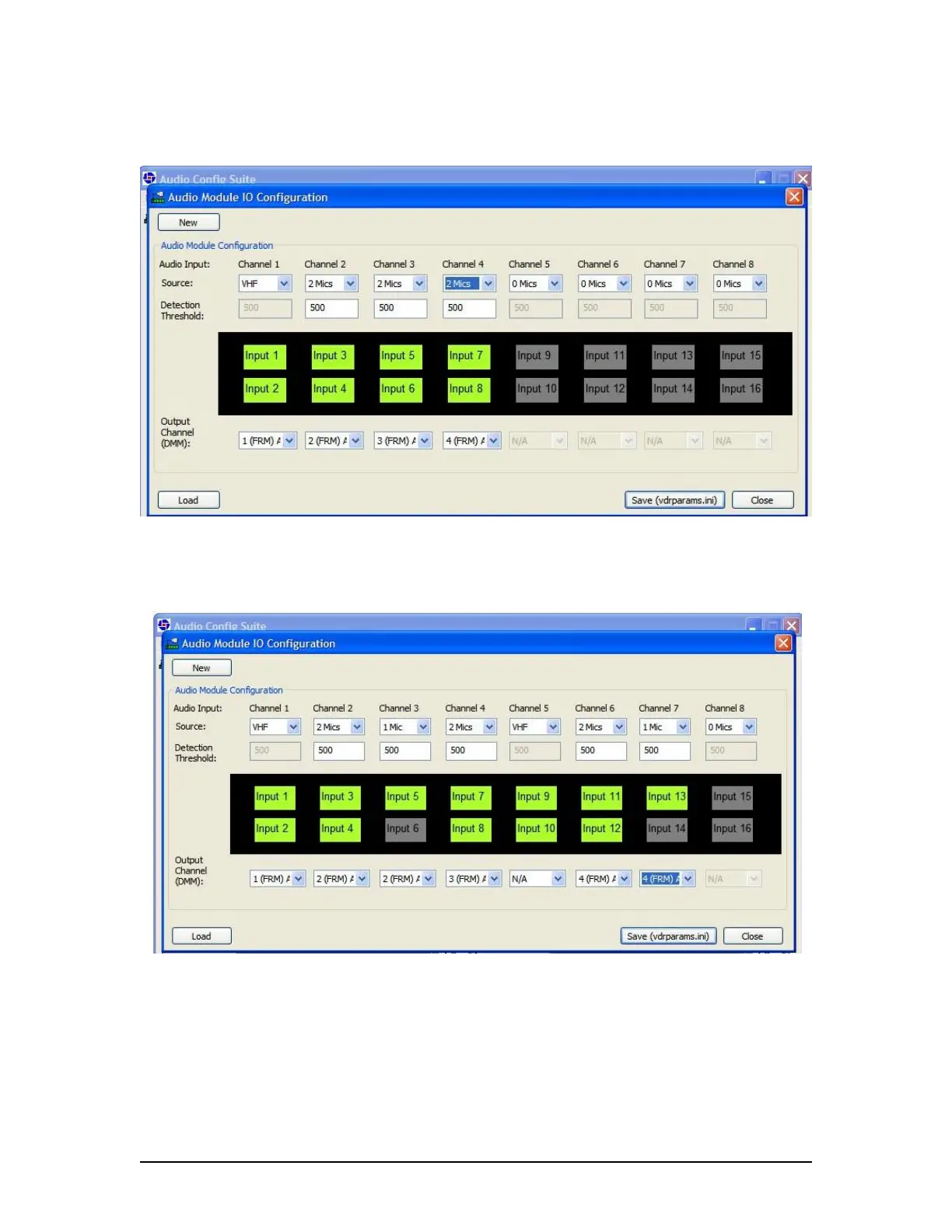
The following figure shows a typical Audio I/O Configuration consisting of Primary VHF and 6
microphones (4 bridge and 2 wing microphones)
Figure 8-21 - Typical VDR configuration: Primary VHF, 4 bridge MICs, and 2 wing MICs.
An Audio I/O configuration consisting of 2 VHF and 8 microphones with software mixing (zones)
is shown in the following figure
Figure 8-22 - Zones software mixing to send all audio source data to the FRM.
8.4.4.4 Detection Threshold Entry Field
In Figure 8-21 - Typical VDR configuration: Primary VHF, 4 bridge MICs, and 2 wing MICs. also
shows a box provided to insert the calculated Detection Threshold value. Refer to Section 8.4.66
– Detection Threshold for instructions on calculating detection thresholds.
VDR-100G3/G3S Installation Manual 06/10/2008
8-24