Chapter 5: Data Acquisition Unit, Rev. 1.1
5.2 INSTALLING THE DAU
The Data Acquisition Unit (DAU) is designed to be bulkhead mounted. It requires a clearance of
at least 400mm from the bottom of the unit to the deck to allow for adequate cable entry spacing.
All other sides of the unit should have a minimum of 100mm clearance to allow for proper
ventilation and maintenance.
The DAU cabinet is installed on the prepared base as shown in Appendix 7: Approval Drawings
at the end of this manual. Alternatively the DAU can be attached directly to the wall.
5.3 DAU Connections
Note! All cabling should be clearly labeled at all connection points to allow for
easier identification, particularly at all VDR-100G3 entry points.
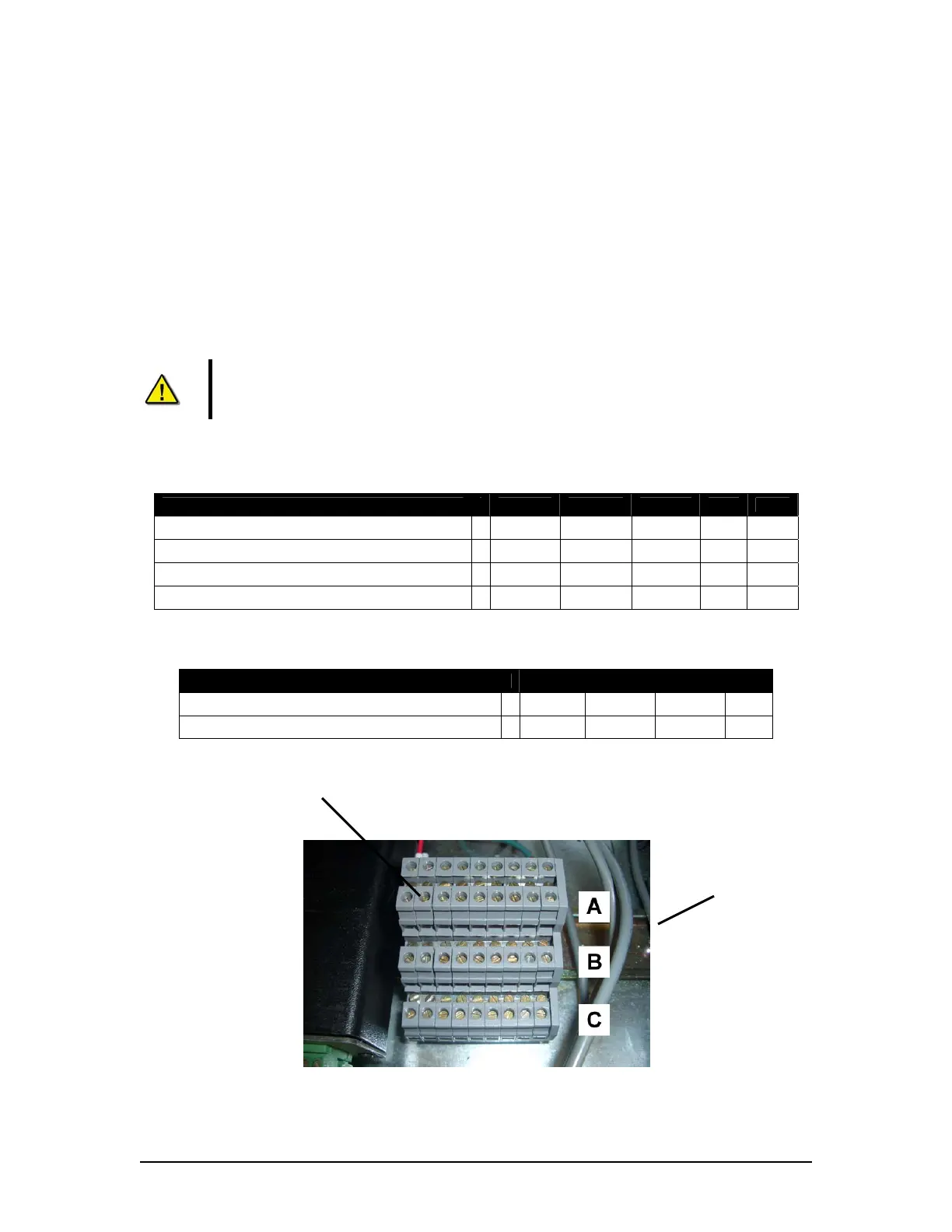
The DAU, when available, contains 6 terminal block connections, broken into two (2) physical
groups:
Devices C B A Term
Video GND Ret - 24+ 25
Hub GND Ret - 24+ 24
NMEA GND Ret - 24+ 23
Audio GND Ret - 24+ 22 EP
Table 5.1 - DAU Terminal Block (One)
Devices C B A Term
Interface 1 GND Ret - 24+ 27
Interface 1 GND Ret - 24+ 26
Table 5.2 - DAU Terminal Block (Two)
DAU Terminal
Block (One)
DAU Terminal
Block (Two)
Figure 5.2 - Terminal Block Letter Labeling
VDR-100G3/G3S Installation Manual 06/10/2008
5-2