Chapter 9: Video Module, Rev. 1.2
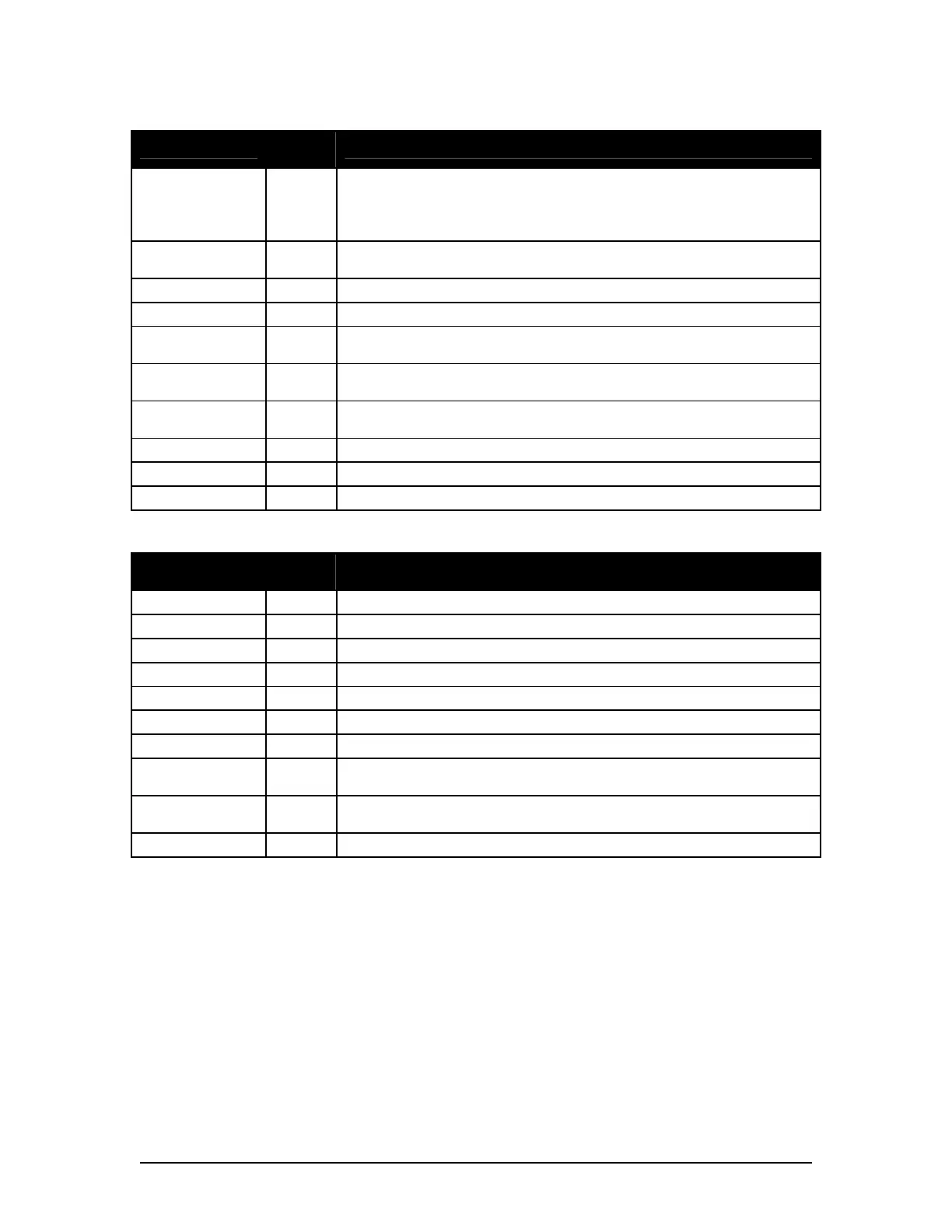
Parameter
Typical
Value
Remarks
HPOL1 1
0 or 1. HSYNC Polarity
- Changing this value will increase margin at the left of the image
- Choose the value which produces the widest margin, and then
adjust with XDim1
VPOL1 1
0 or 1. VSYNC Polarity
Captured images will not be rectangular if incorrect value is chosen
XCLAMPPOL1 -1 -1=Internal, 0= Negative, or 1= Positive.
XCOASTPOL1 1 -1=Internal, 0= Negative, or 1= Positive.
PreCoast1 0
0 to 255. Number of clock synchronization pulses to skip prior to
COAST signal
PostCoast1 0
0 to 255. Number of clock synchronization pulses to skip after
COAST signal
SyncThreshold1
0 to 255. For composite signals only, used to differentiate a VSYNC
from a HSYNC
VCO1 2 Must be present and must be same value as in [CLOCK] section
CPmp1 6 Must be present and must be same value as in [CLOCK] section
N1 0 Must be present and must be same value as in [CLOCK] section
Table 9-4 - SYNCS Parameters
Parameter
Typical
Value
Remarks
RGain1 75 0 to 255. Specifies A/D range for the red video line.
GGain1 75 0 to 255. Specifies A/D range for the green video line.
BGain1 75 0 to 255. Specifies A/D range for the blue video line.
ROff1 128 0 to 255. Specifies DC offset for the red video line.
GOff1 0 0 to 255. Specifies DC offset for the green video line.
BOff1 0 0 to 255. Specifies DC offset for the blue video line.
CVolt1 0 0 = clamp to min voltage. 1 = clamp to midscale.
CPlace1 8
Specifies when clamp occurs in pixel clocks from trailing edge of
HSYNC.
CLength1 20
Specifies number of black pixels that participate in the DC restore
clamp circuitry.
VideoFormat1 1 RADAR = 1, CHART = 2
Table 9-5 - VIDEO Parameters
9.5.1.1 Customize Entries in the VidChanX.ini Files
Each entry in the <VidChanX.ini> file indicates the voltage level, timing, and signal characteristics
of the video source. The values generated by Video Configuration Utility (VCS2) are based on
VESA and Industry Standards and are adequate in order to capture initial images.
If a video capture does not initiate, the most likely reason is that the VPOL1 field may be set
wrong. The Video Configuration Utility (VCS2), If provided with a channel number, will capture
and save a sample image to verify the proper state of the VPOL1 field. The image will be saved
to the filename <TestImage.bmp>. The image will be annotated with a calibration grid to verify
proper video alignment.
In certain rare cases it may be necessary to optimize the video to correct the colour balance.
VDR-100G3/G3S Installation Manual 06/10/2008
9-6