Appendix 2: System Configuration File, Rev. 1.1
2. Click the adjacent “Setup” button and enter the values as shown in Figure A2- 31 - Lever
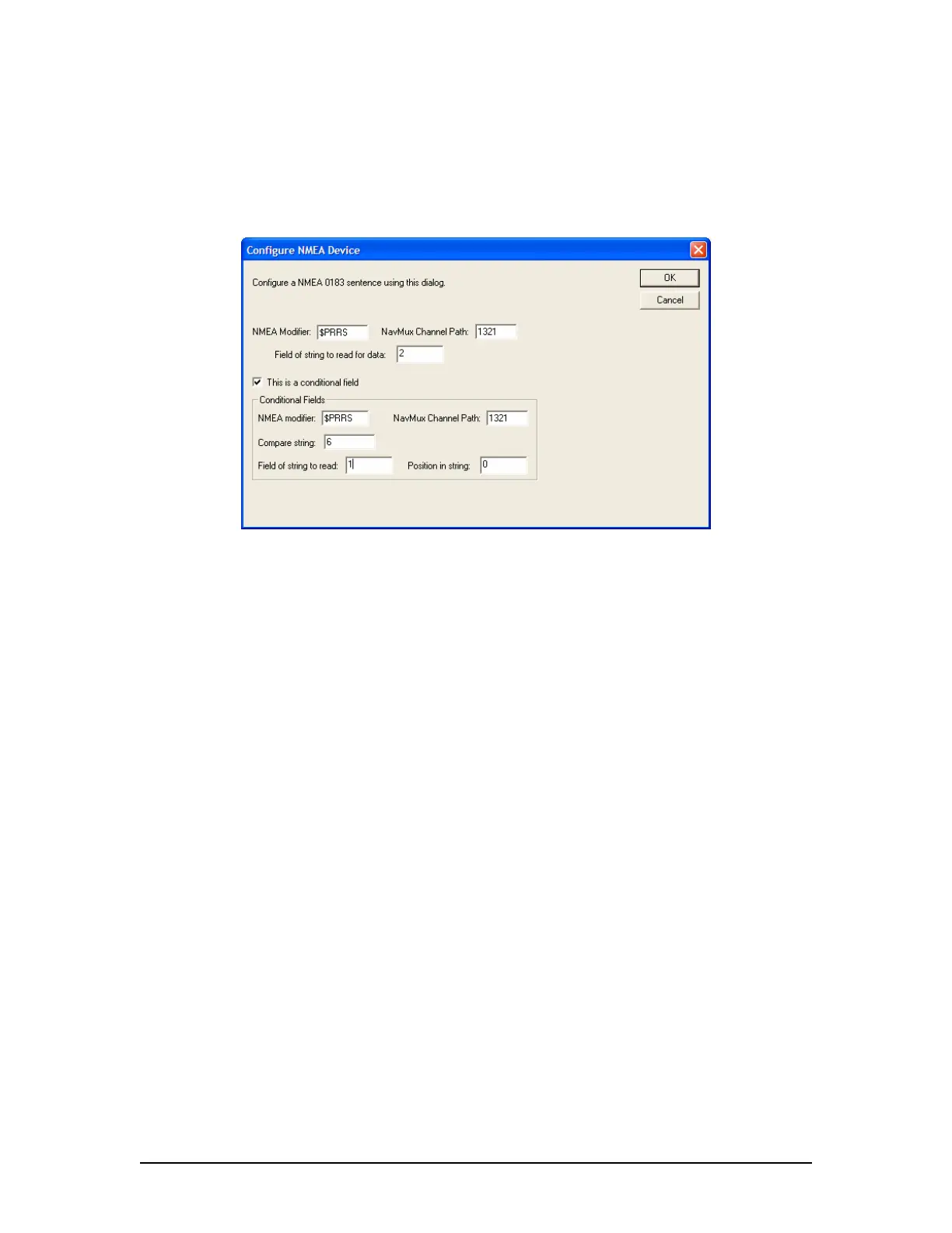
Command Setup – Example1 below. In the Configure NMEA Device window shown in
this figure the target value is specified to read from field 2 if a 6 appears in field 1.
3. Press the “OK” button to save and close the Configure NMEA Device window.
4. Repeat steps 1-3 to configure the RPM Order, Pitch Response, and RPM Response similar
to “Pitch Order” in the steps above.
Figure A2- 31 - Lever Command Setup – Example1
A2.13.3.2 Example 2 – NMEA Data from XDR Sentence
This second example for configuring a NMEA 0183 sentence will use the XDR sentence. This is a
common sentence defined in both the IEC61162 and NMEA 0183 standards. It makes use of tags
or identifiers to broadcast multiple pieces of information using the same sentence. For example,
in a XDR sentence, 4 fields (a, x.x, a, c-c) identify the Transducer Type, Measurement, Units of
Measurement, and Transducer ID. These 4 fields may be repeated up to 6 times (for a total of 24
fields) in 1 string.
$--XDR,a, x.x, a, c—c,………………..,a, x.x, a, c—c,*hh<CR><LF>
| | | |
| | | ------------ Transducer ID (Tag)
| | ------------ Units of measurement
| -------- Measurement
--------- Transducer Type, Transducer #1
In this case, the XDR sentence can be broadcast multiple times from the same system to display
values. For example:
11$ERXDR,T,78.0,R,MC042,T,78.1,R,MC043*58
In this case, view the groups of 4.
T – transducer type = Tachometer
0 – measurement = 78.0
R – units = R = RPM
MC042 – Transducer ID tag identifying engine actual RPM (this will vary between systems).
In the sample XDR string above a second measurement appears in the second group of 4 fields,
possibly indicating engine ordered RPM.
VDR-100G3/G3S Installation Manual 06/10/2008
34