Chapter 12: Final Recording Medium Setup, Rev. 1.5
VDR-100G3/G3S Installation Manual 10/12/2008
12 - 6
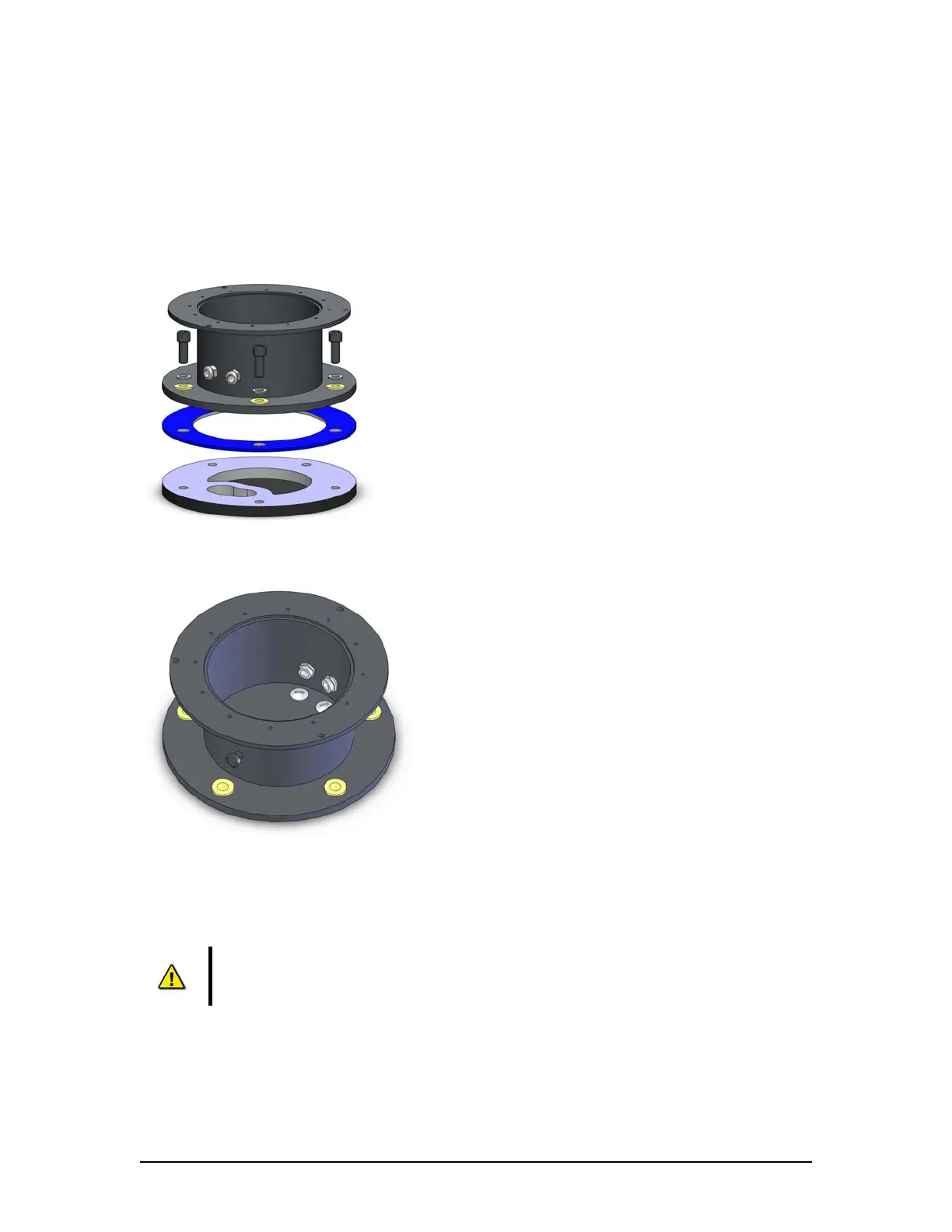
the Rutter Fixed FRM deckmount to it by means of the 5 x M12 bolts supplied. To avoid
corrosion issues, the isolation sleeves as well as the neoprene rubber insulating
plate should always be used.
2. Alternatively (when welding is impossible): drill 5 holes into or through the deck,
optionally tapping M12 holes, and fixing the Rutter Fixed FRM capsule by means of the
e bolts provided. To avoid corrosion issues, the isolation sleeves as well as th
neoprene rubber insulating plate should always be used.
Figure 12–3- Fastening the deckmount assembly to the deck.
Figure 12–4 - When feeding the cables (through the deck) from the bottom, alternative cable entries may be used by
interchanging the cable glands and blind plates.
2.2.1.3 Connecting the Rutter FRM (RUT-02447) Fixed Capsule
r FRM (RUT-
02447) Fixed Capsule to the VDR-100G3/S is installed through a gooseneck
catio n the VDR-100G3 and the Rutter-FRM (RUT-02447) Fixed
apsule is via the RJ45 connectors (See Figure 12–12 - RJ45 Connector ).
r FRM (RUT-02447)
1
NOTE: It is highly recommended that cables connecting the Rutte
conduit (see Figure 12–1 - Sample VDR-100G3S FRM Installation for a sample
FRM installation.)
n connections betweeCommuni
C
The Rutter (RUT-02447) Fixed Capsule requires no setup or partitioning. It will function correctly
when properly connected. Connection is made as per drawing entitled Rutte