Appendix 6: External Interface Modules, Rev. 1.1
A6.1.3.2 Connection Information
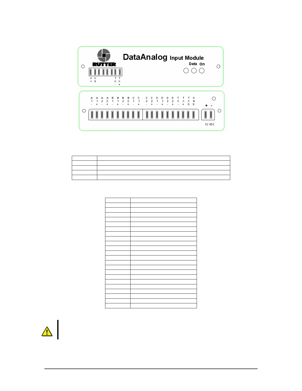
Figure A6 - 2 DataAnalog Front (Top) and Back (Bottom) view
A6.1.3.3 Front panel connection info:
Connector Description
V+ 12VDC Input power (Also Available on the back panel) *
see below
Vo 12VDC Input power common (Also Available on the back panel) *
see below
Tx- RS422 Data Output (neg) (Also Available on the back panel)
Tx+ RS422 Data Output (pos) (Also Available on the back panel)
Table A6 - 1 - Front panel connection information
A6.1.3.4 Back panel connection info **
see below
:
Connector Description
A1- System A input, Channel 1 (neg)
A1+ System A input, Channel 1 (pos)
A2- System A input, Channel 2 (neg)
A2+ System A input, Channel 2 (pos)
B1- System B input, Channel 1 (neg)
B1+ System B input, Channel 1 (pos)
B2- System B input, Channel 2 (neg)
B2+ System B input, Channel 2 (pos)
C1- System C input, Channel 1 (neg)
C1+ System C input, Channel 1 (pos)
C2- System C input, Channel 2 (neg)
C2+ System C input, Channel 2 (pos)
D1- System D input, Channel 1 (neg)
D1+ System D input, Channel 1 (pos)
D2- System D input, Channel 2 (neg)
D2+ System D input, Channel 2 (pos)
Tx- RS422 Data Output (neg)
Tx+ RS422 Data Output (pos)
Tx0 RS232 Data Output (neg)
GND RS232 Data Output (pos)
+ (12VDC) 12VDC Input power
- (12VDC) 12VDC Input power common
Table A6 - 2 - Back panel connection information
* Warning! Connect power to either the front OR rear of the interface. Only one
power input is required.
** Note! Like-lettered system inputs share a common ground. For example, input A1
shares a common ground with input A2. Likewise, B1 shares a common ground with B2,
C1 with C2, and D1 with D2.
VDR-100G3/G3S Installation Manual 06/10/2008
2