Appendix 2: System Configuration File, Rev. 1.1
A2.5.3 Model
Enter the model name of the video capture component.
A2.5.4 Type
From the drop down box select the type of video capture component in relation to the channel
number. Options available for selection are:
S-Band Radar,
X-Band Radar,
ECDIS, and
CCTV.
A2.5.5 Location of Display
Enter the location of the video capture component on the ship.
A2.5.6 Saved to FRM
If the video capture is saved to the FRM, this checkbox must be checked.
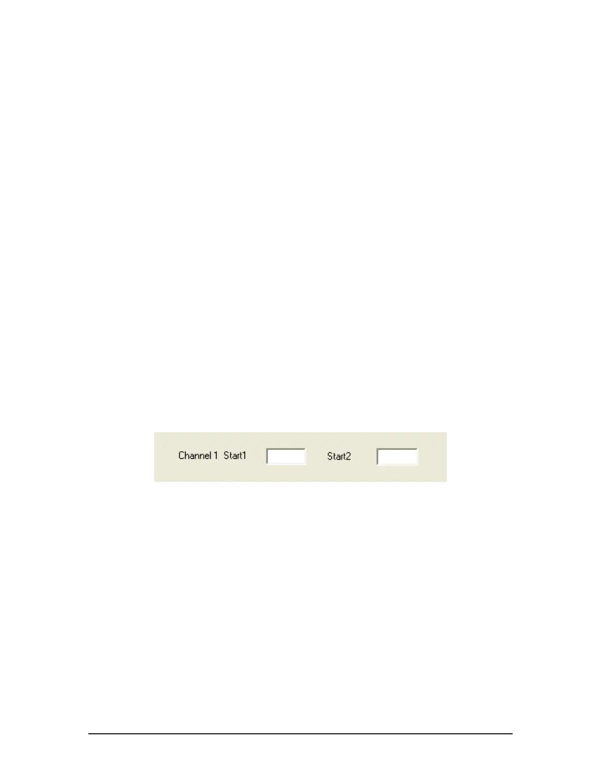
A2.5.7 Interlaced or Interleaved
Selecting the “Interlaced” checkbox disables the “Interleaved” checkbox. Selecting the
“Interleaved” checkbox disables the “Interlaced” checkbox. Depending on which checkbox is
selected, the corresponding Image “Start” text box appears. These “Start” fields correspond to the
start point of the odd and even lines of an interlaced OR an interleaved image. This information is
available via the Rutter Technologies Video Configuration software (see Chapter 9: Video Module
for further information on this software).
Figure A2- 9 - Image Start Points
A2.5.8 Static
Enter the onscreen name of the video capture component.
A2.5.9 Capture Frequency for each Video Channel
Enter the number of seconds between the capture of each image. This number is dependant
upon the number of video sources present:
1 source has a capture interval of 15 seconds,
2 sources have a capture interval of 7.5 seconds,
3 sources have a capture interval of 5 seconds, and
4 sources have a capture interval of 3.75 seconds.
A2.5.10 Other Comments
Enter any additional comments relevant to the video capture aspect of the
configuration/installation.
VDR-100G3/G3S Installation Manual 06/10/2008
11