Chapter 8: Audio Module, Rev 1.1
8.4.4.3 Starting from a Blank Audio Module I/O Configuration Window
The Audio Module I/O configuration is recreated to copy the Audio Module: each input channel
is shown from Channel 1 (inputs 1 and 2) on the left to Channel 8 (inputs 15 and 16) on the
right.
PART 1: Setting the Audio Input Source
These steps identify the types of inputs and the number of inputs connected to the audio module.
Refer to Section 8.3: Audio Connections for details on the physical connections of each input.
Start new I/O configuration by selecting the settings for Channel 1 that match the installation and
work your way right to the highest channel on your module.
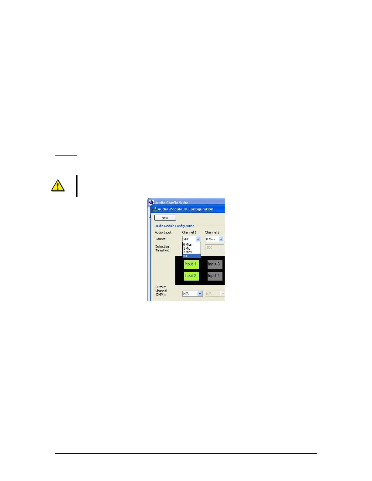
STEP 1:
In the Source drop-down menu (Figure 8-19 - Selecting Channel Source, shows the
Source pull-down selection for Channel 1 being (normally) chosen as VHF) select the types of
Audio Inputs connected to each audio input channel.
NOTE: If there are no microphone connections on an audio input channel set the
Source to “0 Mics”
Figure 8-19 - Selecting Channel Source
VDR-100G3/G3S Installation Manual 06/10/2008
8-22