Chapter 9: Video Module, Rev. 1.2
9.4 Video Module Connecting
The Video Module is connected to the VDR-100G3 via an Ethernet cable and a DC power cable:
• The Ethernet communication output is connected via a crossover through Ethernet cable
to the Video port on the Power Control Center located within the DPU.
• The DC power supply is provided by a connector next to the Video Ethernet port on the
PCC. DC power is connected via 2 conductor power cables to the power input on the
Video Module.
• All connection points are outlined in the following tables.
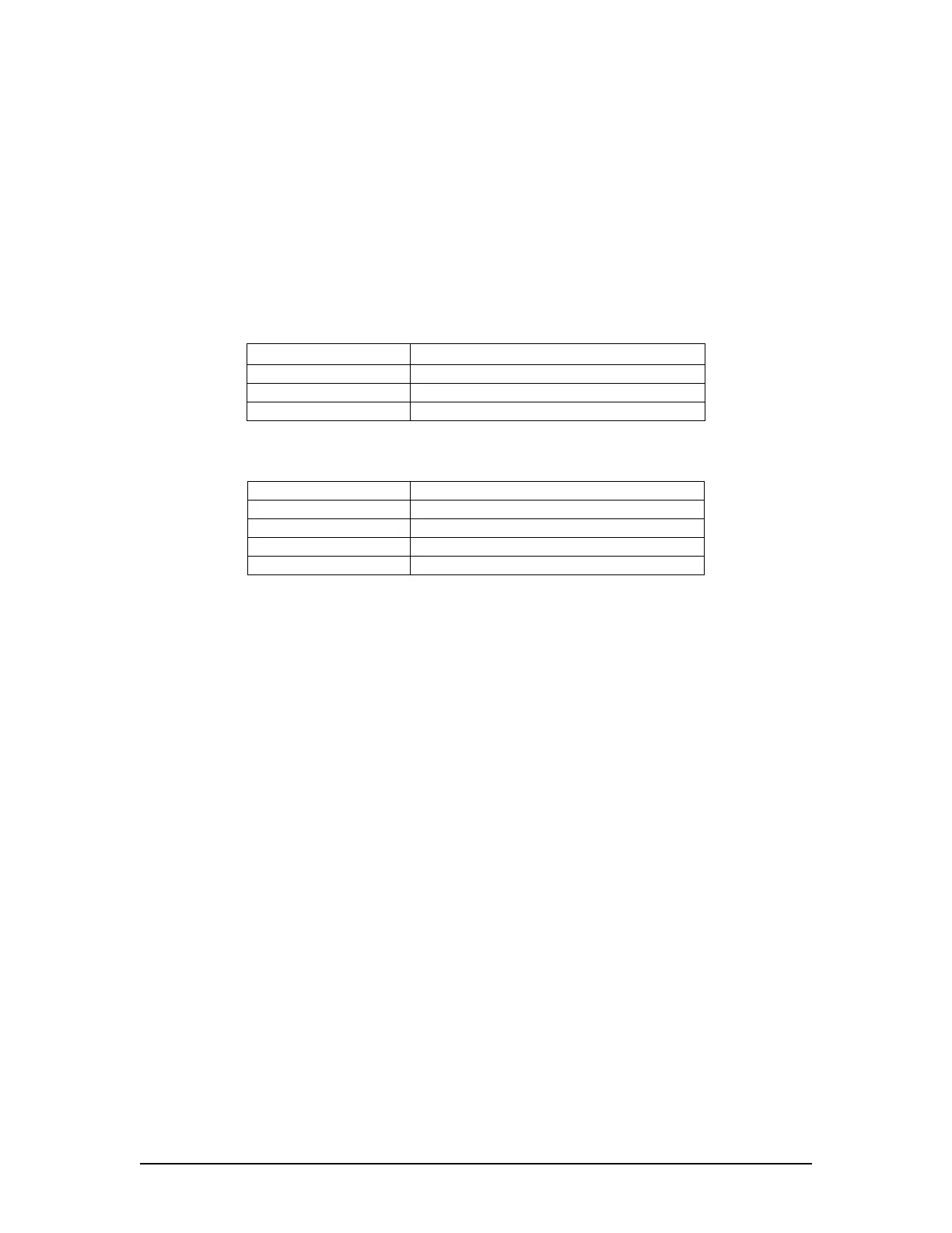
Video Module Front Panel Connection
Connector Description
10-30 VDC+ Input power positive
10-30 VDC- Input power negative
RJ45 connector Ethernet Connection (UDP)
Table 9-1 - Video Module Front Panel Connection
Video Module Back Panel Connection
Connector Description
Video1 Channel 1 Video DB-15HD input
Video2 Channel 2 Video DB-15HD input
Video3 Channel 3 Video DB-15HD input
Video4 Channel 4 Video DB-15HD input
Table 9-2 - Video Module Back Panel Connection
9.5 Video Module Configuring
The required video capture interval is 15 seconds (4 images per minute) for each video source.
To determine the TransferRate divide 15 seconds by the number of video sources (i.e. when
there are 2 video sources set the transfer rate in the <vdrparams.ini> file to 7.5 seconds to ensure
that the primary video source is recorded every 15 seconds. A base VDR system has only one
active video channel (CH-1), additional radar channels may be captured but must be enabled by
a product key.
The DMM initiates the capture of video information and specifies its configuration. This includes:
The video channel to be digitized;
The sources of the vertical and horizontal syncs;
The coefficients for the Phase Locked Loop (PLL) -generated pixel clock (or selection of
an external clock); and
The dimensions (number of samples and lines) of the captured frame.
The VDR-100G3 video capture can be configured using the VDR Params tab in the Video
Configuration Suite (see Section 9.5.6: VDR Params Tab) or the video capture can be configured
manually as follows:
Manually edit the [VIDEO] section of the <vdrparams.ini> file located in the C:\Windows
directory of the DMM to set up basic video information to reflect your installation;
Edit the <VidChanX.ini> file for each video source found in the C:\VDRApps directory on
the DMM to set up the video format and configuration (the VDR-100-G3 Video
Configuration Utility known as VCS2 is used for this set up operation); and
Test input sources first through Video Test within the Record Application and finally by
viewing quality video during playback of downloaded data.
VDR-100G3/G3S Installation Manual 06/10/2008
9-4