8 AUDIO MODULE
Introduction
The Audio Module receives audio information from microphones and vessel radios in
accordance with the IEC 61996.2.and the MSC.163(78) standards. All audio data is sent to the
DMM for processing, storage, and retrieval. This module also controls the buzzers used to test
microphones connected to the VDR-100G3.
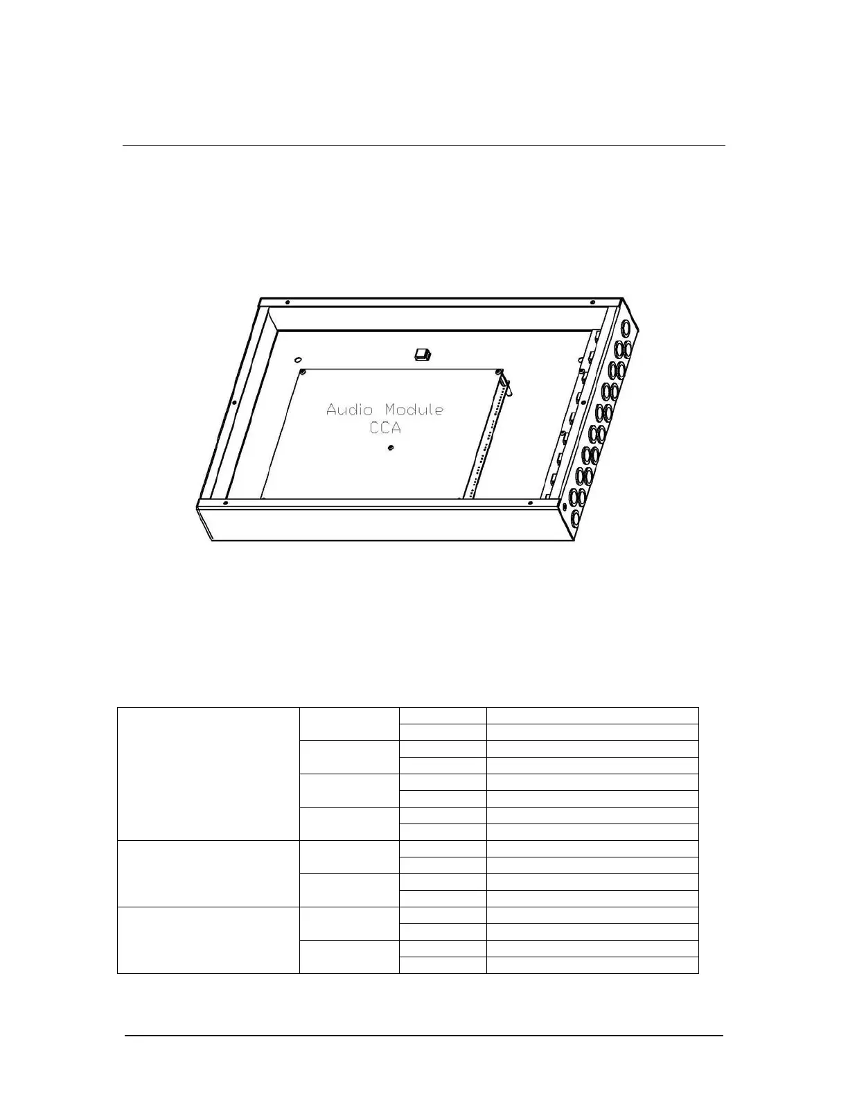
Figure 8-1 - Audio Module Enclosure
8.1 Audio Module Planning
The basic Audio Module contains a 4-channel configuration. Each channel contains 2 inputs.
See table below for more details on the basic and optional channel configurations
Input 1 VHF Tx/Rx or VHF Tx
Channel 1
Input 2 VHF Rx
Input 3 Internal Mic #1 Channel 2
Input 4 Internal Mic #2
Input 5 Internal Mic #3 Channel 3
Input 6 Internal Mic #4
Input 7 External Mic #1
Base - 8 Input Module
Channel 4
Input 8 External Mic #2
Input 9 VHF(2)Tx/Rx or VHF (2)Tx Channel 5
Input 10 VHF(3) Tx/Rx or VHF(2) Rx
Input 11 Internal Mic #5
Optional - 12-Input Module
Channel 6
Input 12 Internal Mic #6
Input 13 Internal Mic #7 Channel 7
Input 14 Internal Mic #8
Input 15 Internal Mic #9
Optional - 16-Input Module
Channel 8
Input 16 Internal Mic #10
Table 8-1 - Audio Module Channel configurations for the basic and optional models.
VDR-100G3/G3S Installation Manual 06/10/2008
8-1