Chapter 8: Audio Module, Rev 1.1
VDR-100G3/G3S Installation Manual 06/10/2008
8-16
8.4.2.1 Setting Line/Mic Input
Select Line input for VHF connections. Select Mic input for microphone connection.
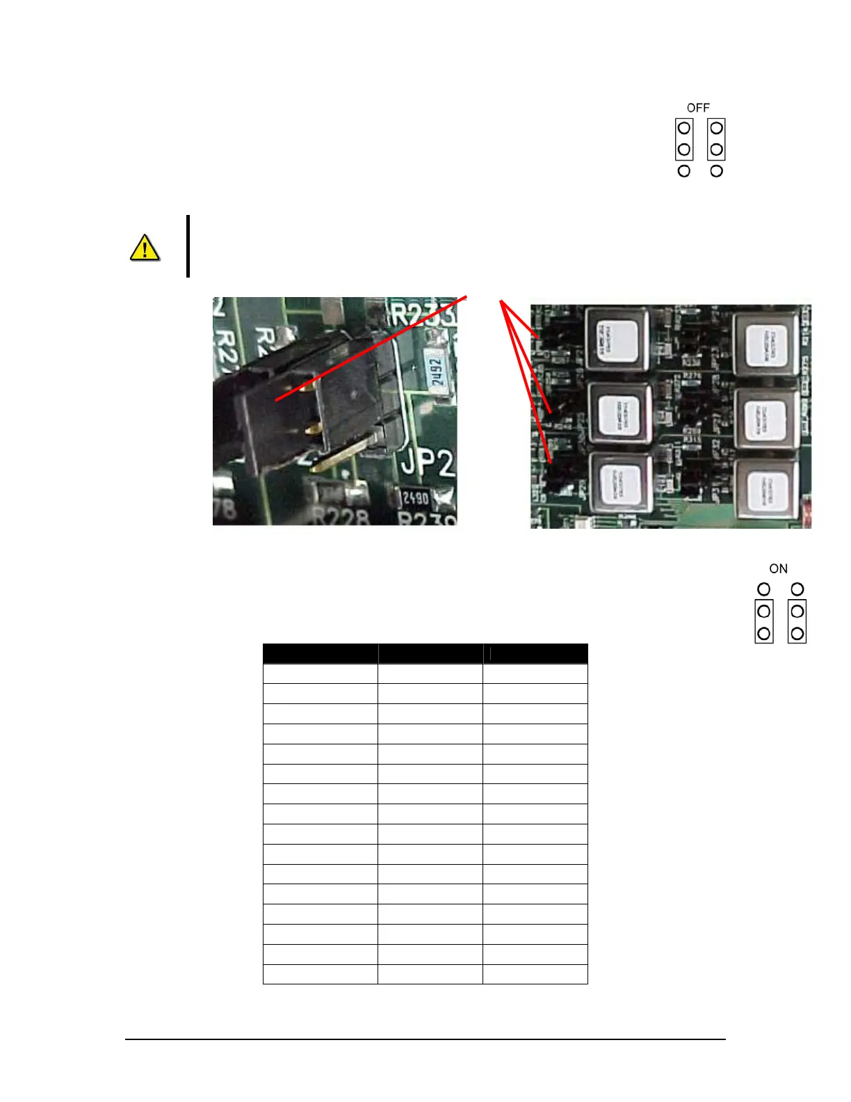
To select Line input, the jumpers for the audio input must be set to OFF. The 2
jumpers must cover the top 4 pins.
Note! The top 4 jumper setting pins are the 4 pins farthest from the phoenix
connectors (located at the rear of the Audio Module circuit card assembly). The
bottom 4 pins are the 4 pins closest to the phoenix connectors. See Figure 8-11 -
Audio Module Internal Processing Board above.
Figure 8-12 - Left is Jumper Close-Up (in OFF position) and Jumpers (long view).
To select Mic input, the jumpers for the audio input must also be switched to ON. The 2 jumpers
must cover the bottom 4 pins. The table below provides information for jumper numbers and
their audio input numbers.
Jumper Input Factory Default
JP 1,2 Input 1 OFF
JP 3,4 Input 2 OFF
JP 5,6 Input 3 ON
JP 7,8 Input 4 ON
JP 9,10 Input 5 ON
JP 11,12 Input 6 ON
JP 13,14 Input 7 ON
JP 15,16 Input 8 ON
JP 17,18 Input 9 OFF
JP 19,20 Input 10 OFF
JP 21,22 Input 11 ON
JP 23,24 Input 12 ON
JP 25,26 Input 13 ON
JP 27,28 Input 14 ON
JP 29,30 Input 15 ON
JP 31,32 Input 16 ON
Table 8-3 - Jumper to Audio Module Input Associations
Jumpers