Chapter 8: Audio Module, Rev 1.1
8.4.2 Audio Module Internal Processing Board
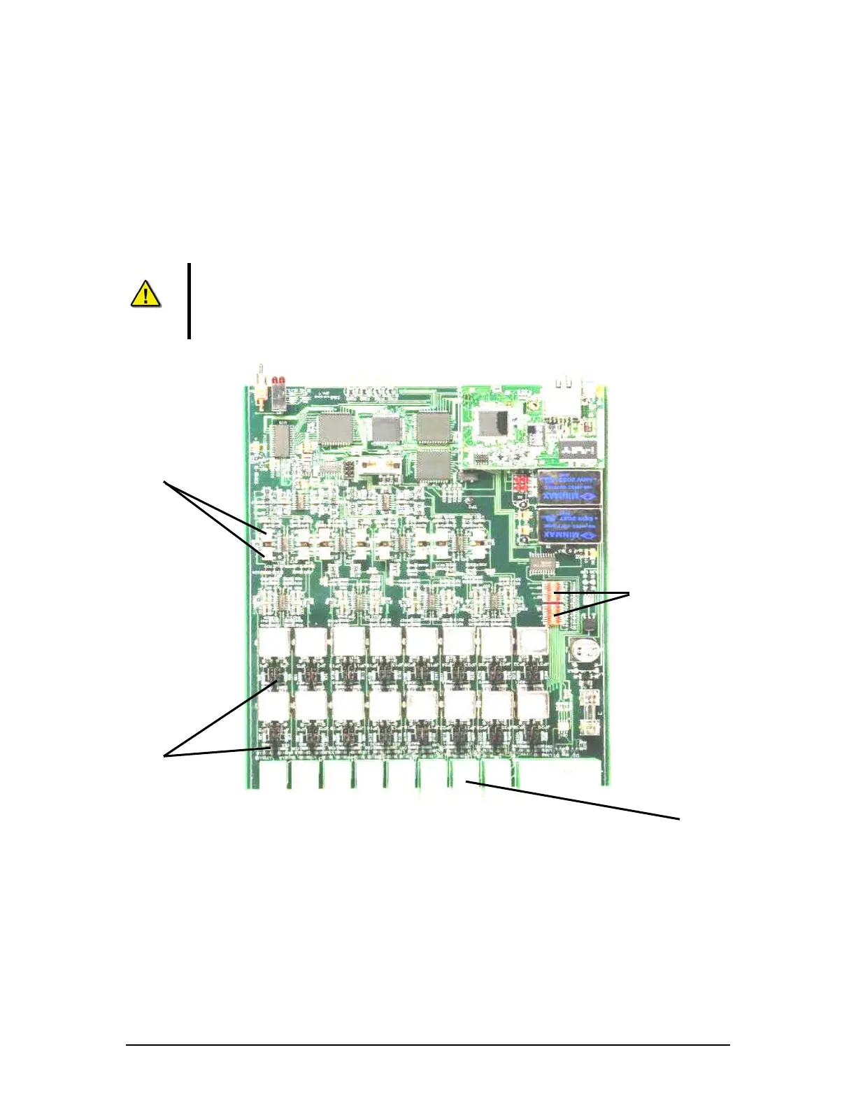
The Audio Module’s internal processing board may need to be configured for each installation.
IMPORTANT! If the Audio Module must be opened DO NOT remove the rear end plate (channel
and buzzer). To access to the Audio Module input circuit card assembly, first remove the front
plate then remove of the black (top) casing. The top casing slides away from the silver
(bottom) casing.
NOTE 1: DO NOT attempt to pull the internal processing board away from the
silver (bottom) casing.
NOTE 2: Before beginning any physical adjustments to the internal processing
board, power must be removed from the Audio Module unit.
FRONT
Potentiometers (Pots)
Phantom Voltage
Switches
Line/Mic Input
Jumpers
REAR
Phoenix
Connectors
Figure 8-11 - Audio Module Internal Processing Board
VDR-100G3/G3S Installation Manual 06/10/2008
8-15