Chapter 9: Video Module, Rev. 1.2
The <vdrparams.ini> file, located in the C:\WINDOWS directory on the DMM, must be edited to
reflect the VDR’s video configuration. The following steps outline how to edit the file to reflect a
ship configuration:
1. Close the VDR_Record software.
2. Open the <vdrparams.ini> file from the Windows desktop.
3. Scroll to the [VIDEO] section and edit the following settings to reflect ship configuration:
a. numSources – the number of video sources to be captured (1 - 4).
b. transferRate – time, in milliseconds, between captures (15000 for 1 video
source, 7500 for 2 video sources, 5000 for 3 video sources, 3750 for 4 video
sources);
c. blocks – images to be stored in each 1-minute block (4 * numSources);
4. Save and close the <vdrparams.ini> file.
5. Select the Commit.exe icon on the DMM’s desktop to save settings and reboot
6. The VDR will restart in MyUser mode with the VDR_Record application running.
Refer to the <vdrparams.ini> appendix of this document for a complete listing of video parameter
settings and their respective descriptions.
9.5.1 Video Channel Configuration File
Each video channel has a separate video channel INI file: <VidChan1.ini>, <VidChan2.ini>,
<VidChan3.ini>, and <VidChan4.ini>; these files are located in the C:\VDRApps directory.
Manual editing of an existing <VidChanx.ini> file is generally not done unless the file fails to
provide an adequate initial capture. This may be the case whereby a <VidChanx.ini> file is
copied/supplied from a previous successful radar connection and the file fails to provide an
adequate image capture on a new connection of the same type of radar.
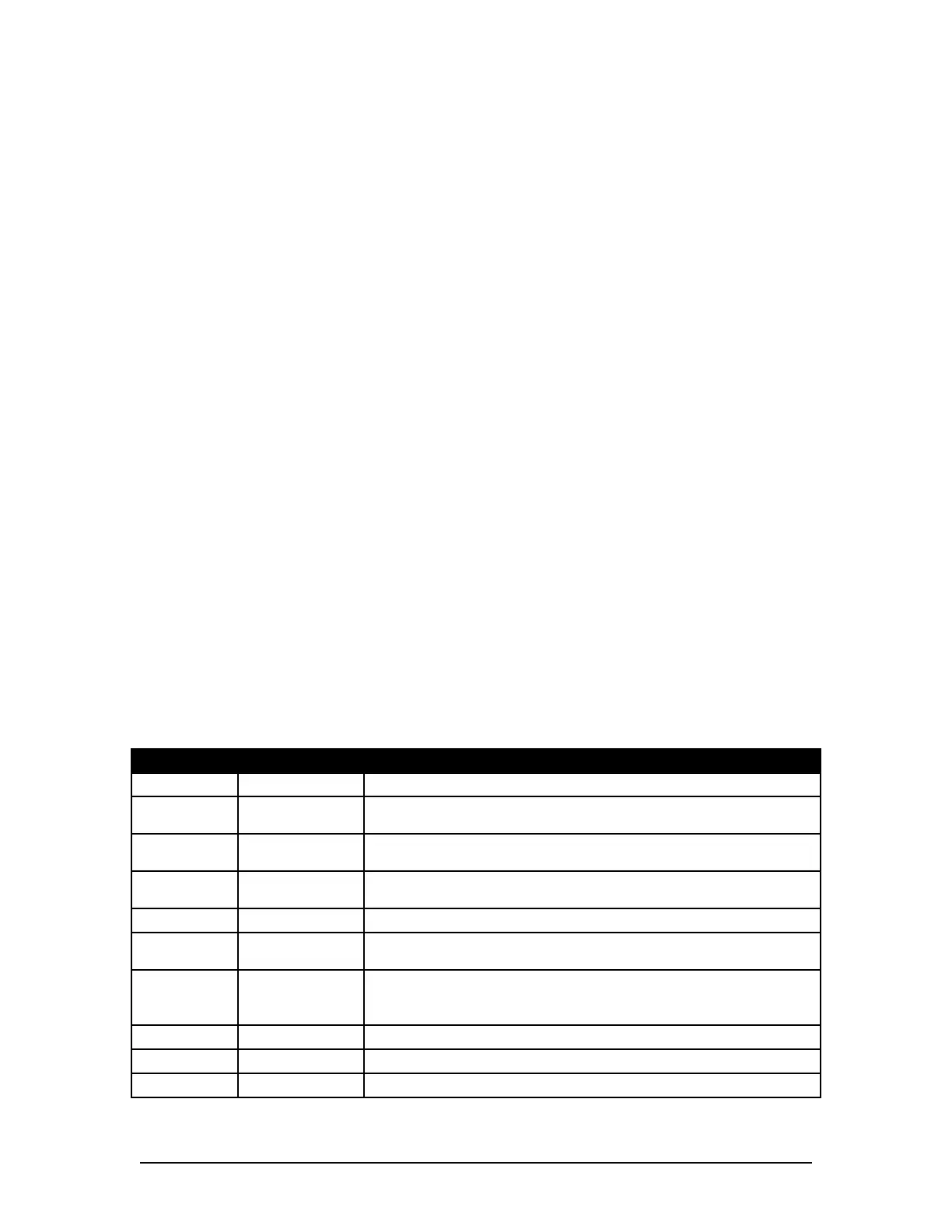
Below is a list of the contents within a <VidChanx.ini> file and their meaning.
Parameter Typical Value Remarks
HsRate1 80.0 HSYNC rate in kHz for default source
Pclk1 135.0
The exact pixel clock frequency (in MHz)for the system (as
specified by the display’s manufacturer)
VCO1 2
Normally set based on the pixel clock rate (0=12-37MHz, 1=37-
74MHz, 2=74-140MHz, 3=140-170MHz)
CPmp1 6
0 to 7. Normally set based on values reported from
<VideoConfigSuite.exe>
N1 0 If set to zero, defaults to PClk1*1000/HsRate1
Phase1 0
0 to 31: Sharpens the image by accommodating for delays due
to cable length and stray capacitance.
XDim1 1288
Sets the captured width. It's recommended to set the
XDimension 8 larger that the desired image, since the X-offset
is adjustable only in multiples of 8.
XOffset1 300 Shifts the image to remove black pixels at left edge.
YDim1 1024 Sets the captured height.
YOffset1 40 Shifts the image to remove black lines from top.
Table 9-3 - CLOCK Parameters
VDR-100G3/G3S Installation Manual 06/10/2008
9-5