Appendix 6: External Interface Modules, Rev. 1.1
A6.2.1.4 Input Configuration
Each DataDiscrete input channel can be configured to monitor high or low voltage signals by
placing or removing jumpers on the DataDiscrete circuit board. Each input channel has an
associated jumper, which changes the input impedance according to the voltage to be monitored.
To access these jumpers:
Unplug the front panel input connectors;
Unscrew the two (2) screws located on the front panel of the DataDiscrete enclosure in
order to remove the panel;
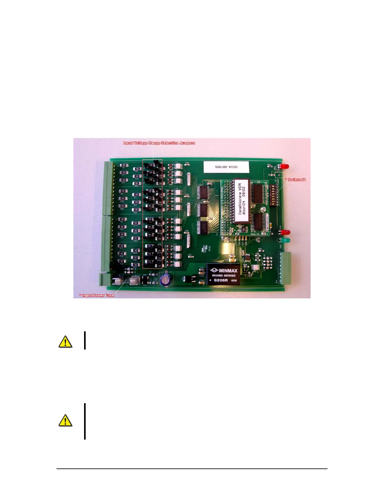
Slide the circuit board out of the enclosure. See DataDiscrete PCB above for location of
the input voltage range selection jumpers.
Figure A6 - 6 -DataDiscrete PCB
The jumpers for input range are labelled JP1 to JP24 on the DataDiscrete input circuit board.
NOTE: The jumpers are located in line with each channel. Numbering is not
consecutive.
The input voltage range is configured as follows:
Jumpers On: Low Voltage input (3 to 50V)
Jumpers Removed: High Voltage input (25 to 140V)
Warning! Exceeding the selected voltage range will damage the
DataDiscrete.
NOTE! The DataDiscrete will not indicate the presence of voltages below the low
end of the selected range. Exceeding the selected voltage range will damage the
DataDiscrete.
VDR-100G3/G3S Installation Manual 06/10/2008
11