Chapter 5: Data Acquisition Unit, Rev. 1.1
VDR-100G3/G3S Installation Manual 06/10/2008
5-4
5.3.2 Video Input Connections
The video inputs are connected via the female BNC bulkhead connectors located at the bottom of
the DAU. All video data is connected to the DAU using RG-11, RG-6, or other approved coaxial
cable. Additionally, the number of cables used is dependant upon the video source:
A composite video source may have a single video cable (with video and sync
combined).
A colour radar source may have five (5) video cables (red, green, blue, H-sync, and V-
sync separately).
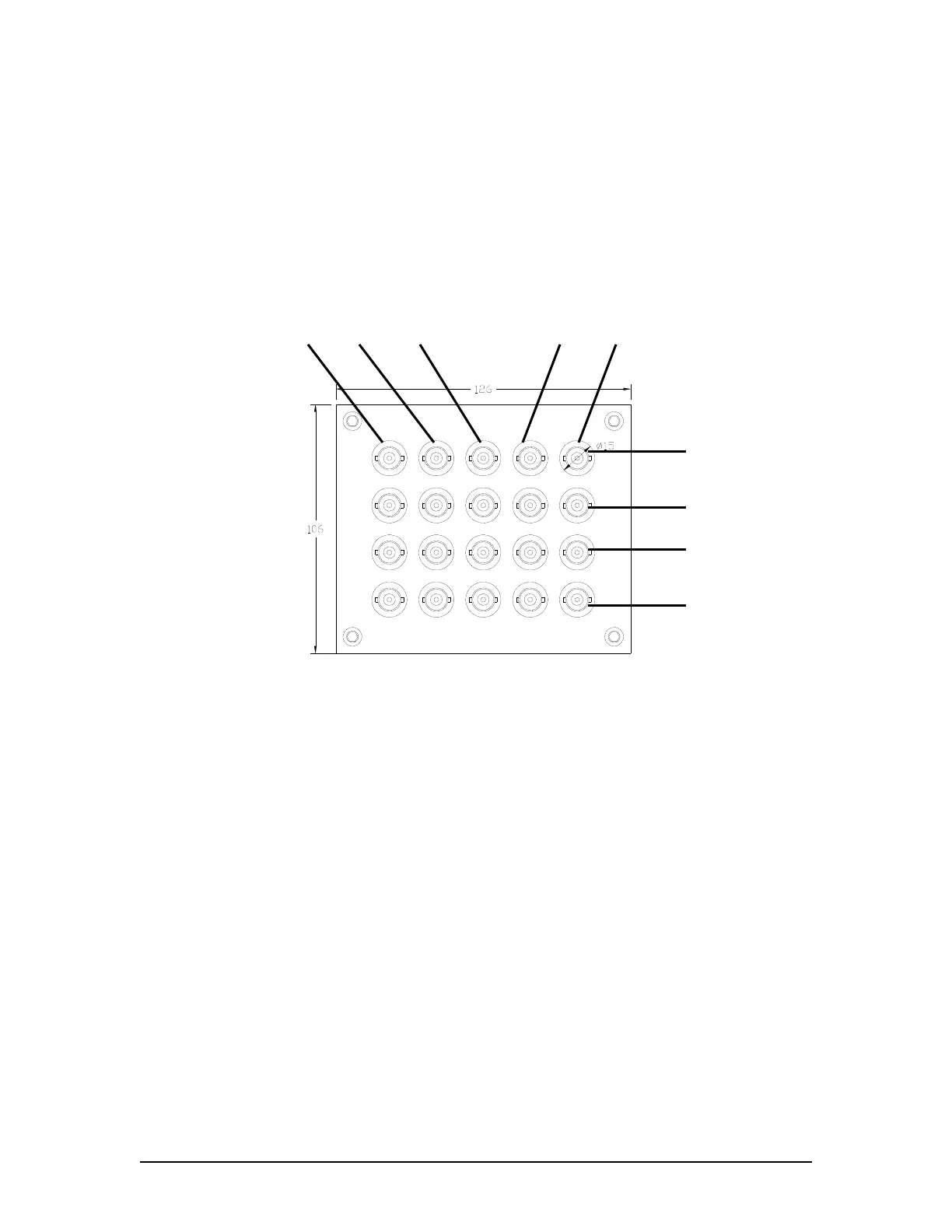
R (Red) G (Green) B (Blue) H (Horiz) V (Vert)
Channel 4
Channel 3
Channel 2
Channel 1
Figure 5.4 - DAU Video Input Connections
Coaxial video cables from the vessel’s video source must be fitted with male BNC connectors.
These are then connected to the appropriate BNC female bulkhead connectors.
NOTE: If the video feed occurs over multiple cables, it is important to ensure that all video cables
are connected to the bulkhead connectors that match the correct signal type (i.e., red=red,
green=green, blue=blue, etc.).