Chapter 8: Audio Module, Rev 1.1
8.5.2 Microphone Installation – Sample 2
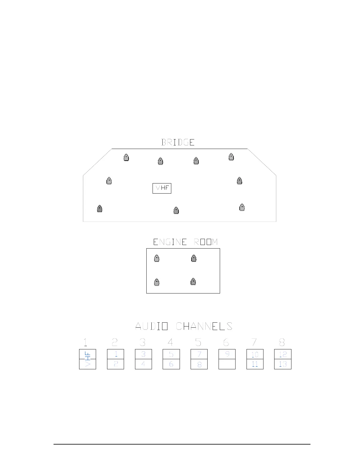
Ship Sample 2 has 9 Internal Microphones installed on the bridge and 4 Internal Microphones
installed in the engine room. There is 1 VHF source.
NOTE: in Figure 8-34 - Sample Audio Module Connections for Ship Example 2 below that Mics 1
and 2 are connected to Channel 2, Mics 3 and 4 are connected to Channel 3, and Mics 5 and 6
are connected to Channel 4, Mics 7 and 8 are connected to Channel 5, and Mic 9 is connected to
the top input of Channel 6. The 4 interior microphones located in the engine room (10, 11, 12,
and 13) are connected to Channels 7 and 8. Since the 4 engine room mics are located in a
separate section of the ship from the 9 Bridge mics, they are not placed on the same channel
as the Bridge mics.
Microphone
9
Microphone
1
2
Microphone
Microphone
3
Microphone
4
Microphone
5
Microphone
6
Microphone
7
Microphone
8
Microphone
10
Microphone
12
Microphone
11
Microphone
13
Figure 8-33 - Sample Mic Layout for Ship Example 2
Figure 8-34 - Sample Audio Module Connections for Ship Example 2
VDR-100G3/G3S Installation Manual 06/10/2008
8-41