Chapter 8: Audio Module, Rev 1.1
8.5 Audio Installation Examples
Provided below are 2 examples for adjusting the <vdrparams.ini> file to properly represent the
microphone installation.
It is important to remember that only the channels specified in the first 4 OutputChannel fields
(OutputChannel1, OutputChannel2, OutputChannel3, and OutputChannel4) of the
<vdrparams.ini> file are saved to the FRM. A user can enter a maximum of 2 channels in one
OutputChannel field. For example, OutputChannel2 may mix Channel 2 and Channel 3. Since the
first OutputChannel field must be used for the VHF, this allows information from a maximum of 12
microphones to be secured to the FRM.
8.5.1 Microphone Installation - Sample One
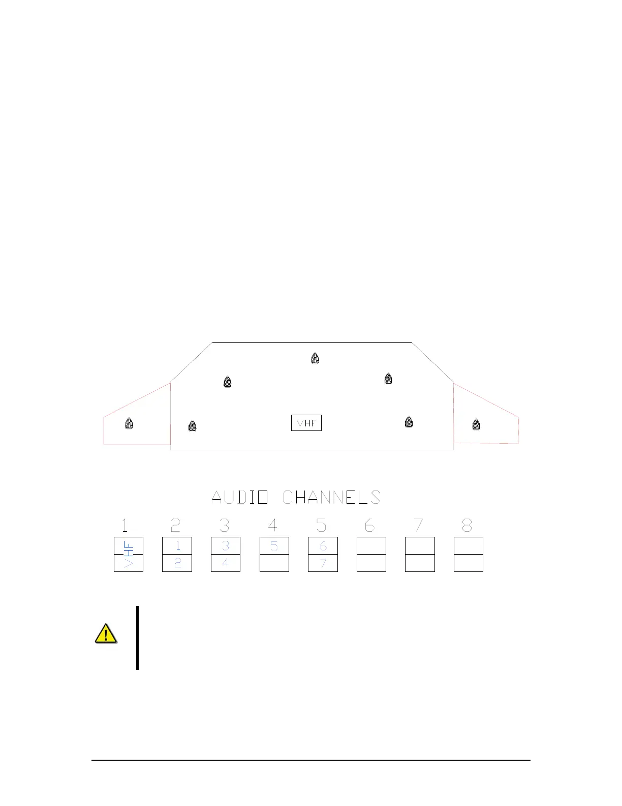
Ship Example 1 has 5 Internal Microphones and 2 External Microphones installed on the bridge.
There is a single VHF source.
NOTE: In Figure 8-32 - Sample Audio Module Connections for Ship Example 1 below that Mics 1
and 2 are connected to Channel 2, Mics 3 and 4 are connected to Channel 3, and Mic 5 is
connected to the top input of Channel 4. The 2 exterior mics (6 and 7) are connected to Channel
5. An external microphone must not be placed on the same channel as an internal microphone.
Stbd Bridge
Wing
Port Bridge
Wing
Microphone
3
Microphone
6
Microphone
1
Microphone
7
Microphone
5
Microphone
4
2
Microphone
Figure 8-31 - Sample Mic Layout for Ship Example 1
Figure 8-32 - Sample Audio Module Connections for Ship Example 1
Note! In this example, the vessel has only 1 VHF. Microphones are shown
connected to Audio Module Channel #5, so that channel must be reconfigured for
external outdoor microphone by assessing the internal processing board. The
Phantom Voltage DIP-Switch and Jumper setting must be set to ON, and the
resistance value of associated potentiometers (pots) must be adjusted down.
VDR-100G3/G3S Installation Manual 06/10/2008
8-39