Chapter 10: NMEA Module, Rev. 1.3
10.4 NMEA Module Connection
The NMEA Module is connected to the VDR-100G3 via an Ethernet cable and a DC power cable.
The Ethernet communication output is connected via a crossover through Ethernet cable
to NMEA port on the PCC located within the DPU.
The DC power supply is provided by a connector next to the NMEA Ethernet port on the
PCC, and connected via a two conductor power cable to the power input on the NMEA
Module.
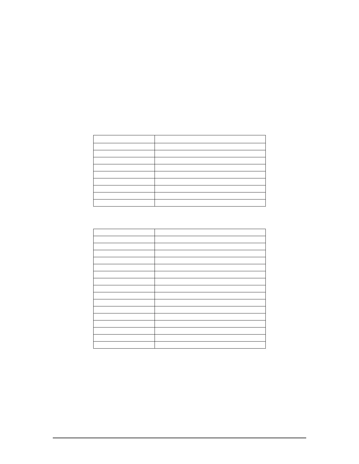
All connection points are outlined in the following tables:
NMEA Module Front Panel Connection
Connector Description
10-30 VDC+ Input power
10-30 VDC- Input power common
RS422 In+ RS422 Data Input (pos)
RS422 In- RS422 Data Input (neg)
RS422 Out+ RS422 Data Output (pos)
RS422 Out- RS422 Data Output (neg)
RS232 Out+ RS232 Data Output (pos)
RS232 Out- RS232 Data Output (neg)
RJ45 connector Ethernet Connection (UDP)
Table 10-1 - NMEA Module Front Panel Connection
NMEA Module Back Panel Connection
Connector Description
RX1+ Channel 1 RS232/422 input (pos)
RX1- Channel 1 RS232/422 input (neg)
RX2+ Channel 2 RS232/422 input (pos)
RX2- Channel 2 RS232/422 input (neg)
RX3+ Channel 3 RS232/422 input (pos)
RX3- Channel 3 RS232/422 input (neg)
RX4+ Channel 4 RS232/422 input (pos)
RX4- Channel 4 RS232/422 input (neg)
RX5+ Channel 5 RS232/422 input (pos)
RX5- Channel 5 RS232/422 input (neg)
RX6+ Channel 6 RS232/422 input (pos)
RX6- Channel 6 RS232/422 input (neg)
RX7+ Channel 7 RS232/422 input (pos)
RX7- Channel 7 RS232/422 input (neg)
RX8+ Channel 8 RS232/422 input (pos)
RX8- Channel 8 RS232/422 input (neg)
Table 10-2 - NMEA Module Back Panel Connection
VDR-100G3/G3S Installation Manual 15/01/2009
10-4