Chapter 9: Video Module, Rev. 1.2
9.3 Video Module Mounting
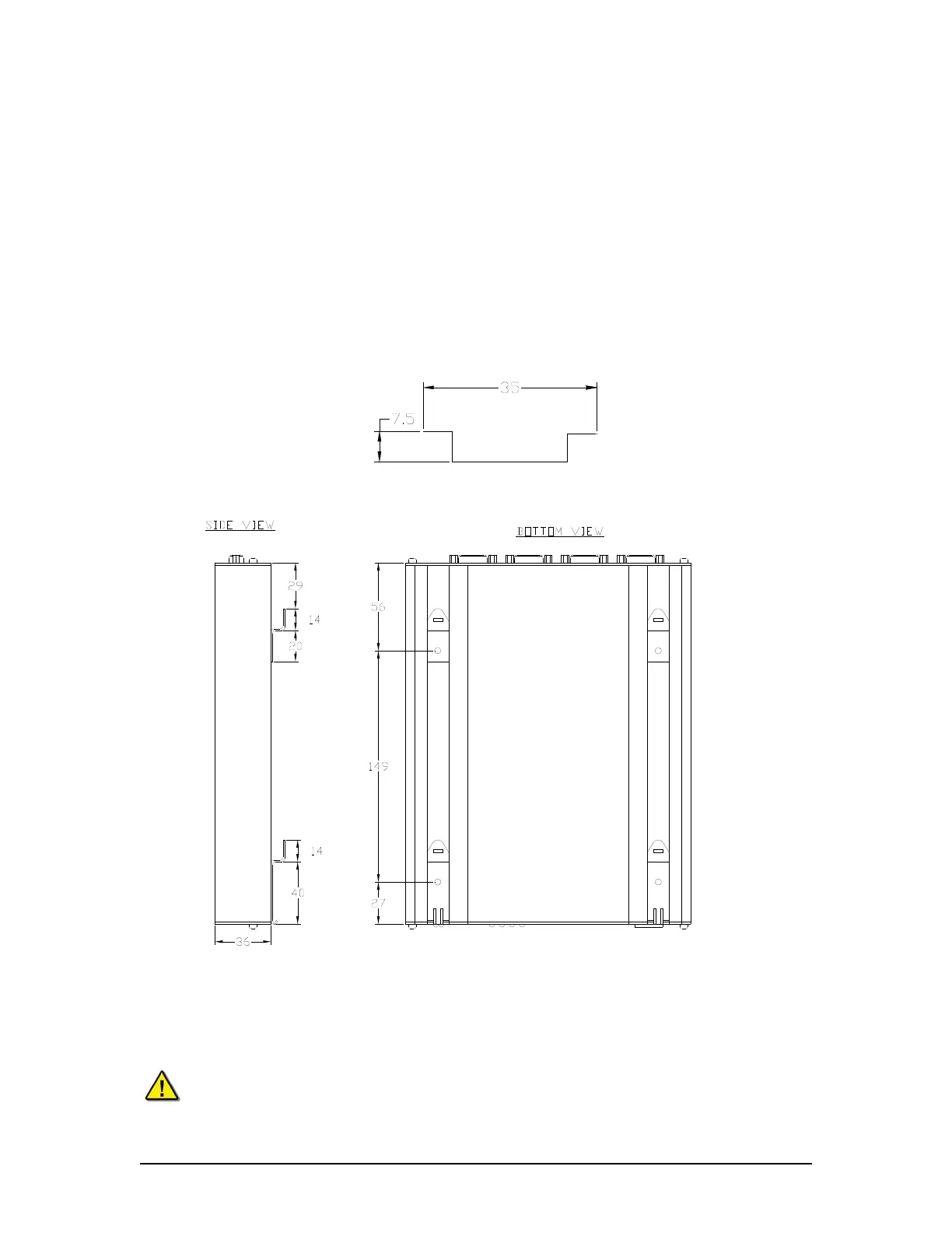
The Video Module is designed to be mounted on two rows of 35mm “Top Hat” style DIN Rail
available on the optional Rutter Data Acquisition Unit (DAU). If there is no DAU then, before the
Video Module can be mounted, two strips of DIN Rail must be installed. The module is held in
place with clips on the back.
NOTE: The DIN Rail is NOT supplied with the Video Module.
Figure 9-2- DIN Rail shows the typical dimensions of the DIN Rail required for mounting an
external interface. It is acceptable to use a DIN Rail deeper than 7.5mm (15mm deep DIN rail is
commonly available), but the 35mm width must be maintained.
Figure 9-2- DIN Rail
Figure 9-3 - Video Module DIN Rail Clips
Alternative mounting method would be to remove the 4 DIN Rail clips from the back of the Video
Module and use 2 strips of high-quality heavy-duty Velcro (not supplied) to attach the Video
Module to a clean and dry prepared surface within the radar cabinet.
Note! The Video Module must be grounded firmly to the ship using the ground stud
on the rear of the module. This grounding must be done regardless of which
mounting method is chosen by the installer.
VDR-100G3/G3S Installation Manual 06/10/2008
9-3