Chapter 11: OPERATION and ALARM UNIT TEST and USER GUIDE
VDR-100G3/G3S Installation Manual 06/10/2008
11-11
1. When the USB Memory Stick is ejected and physically removed from the system, and
then re-connected, the VDR will erase all the data on the USB Memory Stick and begin
recording data to it again;
2. When data is downloaded or copied to the USB Memory Stick, if the drive is NOT ejected
and physically removed within 1 hour after the download is complete, then the VDR will
erase all data on the USB Memory Stick and begin recording data to it again;
3. When the USB Memory Stick is unplugged from the system, without first ejecting it, and
then it is re-connected, then the VDR will erase all data on the USB Memory Stick and
begin recording data to it again;
4. When attempting to download or copy a data set to the USB Memory Stick, if there is
insufficient memory, then the VDR will erase all data on the USB Memory Stick in an
attempt to free enough memory for the download to succeed.
11.14 Connecting the USB Memory Stick
To connect the USB Memory Stick, insert it into the available USB port. The system will detect
the drive and the OAU will display a USB Memory Stick status of “USB: STBY”. After at least 10
seconds, the system will begin recording to the USB Memory Stick and the OAU will display a
USB Memory Stick status of “USB: REC”.
Once the USB Memory Stick RSM is physically connected, the DMM will
automatically detect it and begin the recording process to it. As part of this process,
all data on the USB Memory Stick will be deleted.
11.15 Connecting the RSM
To connect the RSM, once the USB Memory Stick has been properly ejected and physically
removed, complete the following steps:
1. Attach the USB 2.0 cable from the RSM to the USB 2.0 port in the compartment in the
front panel of the DPU;
2. Connect the AC power cable to the RSM;
3. Power on the RSM (switch RSM Power to “On” position);
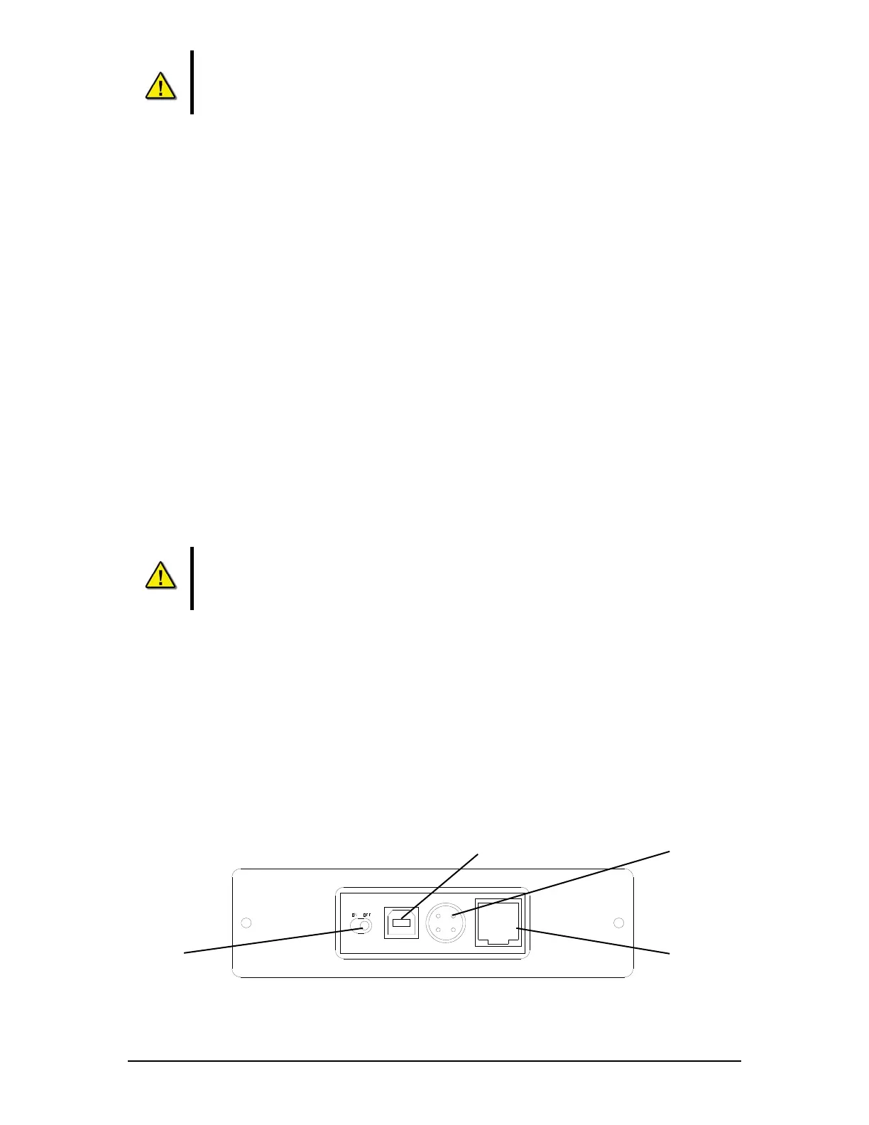
Figure 11–6 - Rear View of RSM Unit
Power Input
Ethenet Port
(Not Used)
Power Switch
USB 2.0 Input