Chapter 8: Audio Module, Rev 1.1
For example, an indoor microphone connected to Channel 2, Input 3 would connect to Buzzer 1
connection point #1 (positive and negative). An indoor microphone connected to Channel 2 Input
4 would connect to Buzzer 2 connection point #6.
If the Audio Module has 16 Channels, it will be necessary to connect two (2) microphone buzzer
connections to one (1) buzzer connection point. For example, Input 14 and 16 can both be
connected to buzzer connection point #10, while Input 13 and 15 can both be connected to
buzzer connection point #5.
Note! The Audio Module must be grounded to the ship if installed outside the DAU.
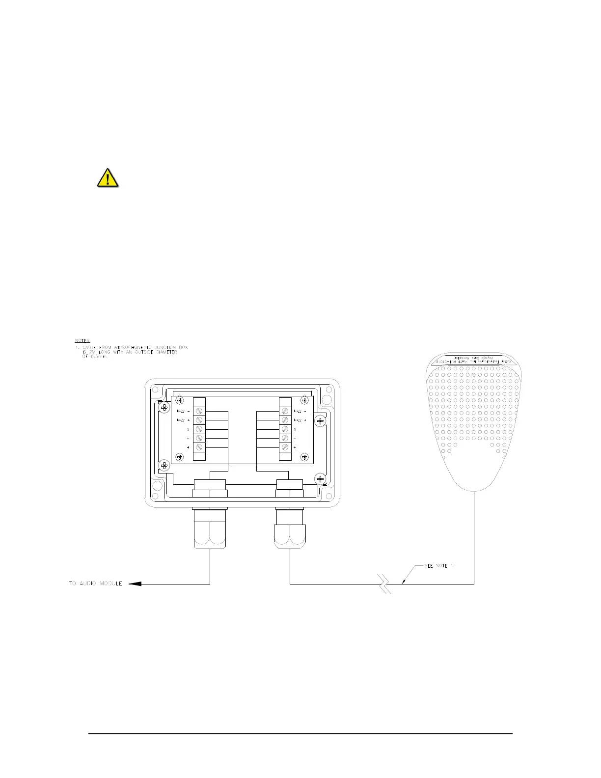
8.3.4 External (Outdoor) Microphone Assembly
The external microphone assembly consists of an outdoor microphone,(which includes an audio
test source or buzzer), and wiring junction box. See Figure 8-5 - External (outdoor) Microphone
and Junction Box for an illustration of the microphone and junction box.
The interconnections required for the external microphone assembly are similar to the internal
microphone as described in Sections 8.3 – Audio Connections, 8.3.2 - Audio Module Inputs, and
8.3.3 –.Buzzer Connections above.
Figure 8-10 - External Microphone Terminal Block
VDR-100G3/G3S Installation Manual 06/10/2008
8-13