Chapter 12: Final Recording Medium Setup, Rev. 1.5
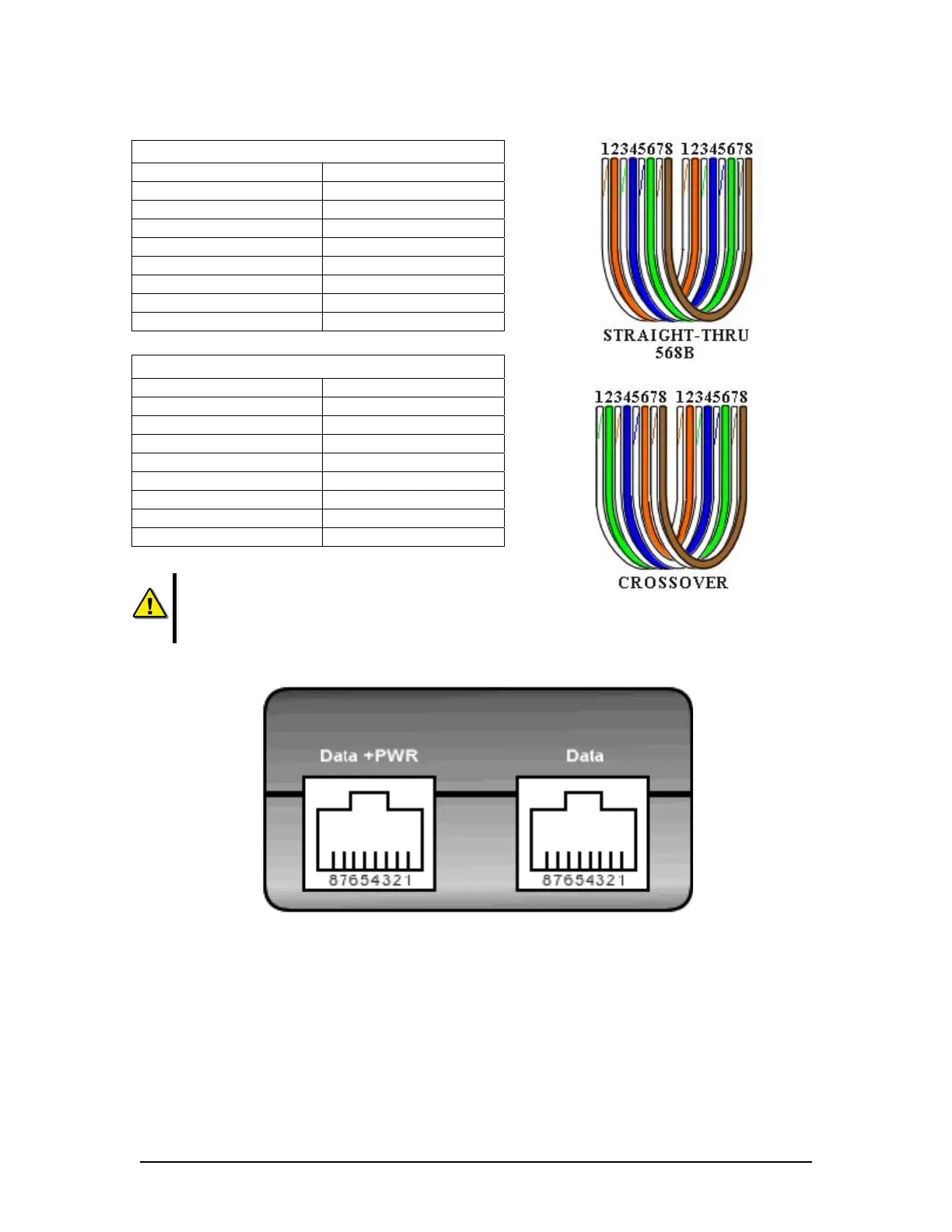
Straight through 568B
Connector 1 Connector 2
1 Tx+ white/orange 1 Tx+ white/orange
2 Tx- orange 2 Tx- orange
3 Rx+ white/green 3 Rx+ white/green
4 N/A 4 N/A
5 N/A 5 N/A
6 Rx- green 6 Rx- green
7 N/A 7 N/A
8 N/A 8 N/A
Table 12-9 Straight-through Ethernet cable set ups
Crossover
Connector 1 Connector 2
1 Tx+ white/orange 1 Tx+ white/green
2 Tx- orange 2 Tx- green
3 Rx+ white/green 3 Rx+ white/orange
4 N/A 4 N/A
5 N/A 5 N/A
6 Rx- green 6 Rx- orange
7 N/A 7 N/A
8 N/A 8 N/A
Table 12-10 – Cross-over Ethernet cable set ups
NOTE: It is highly recommended that cabling connecting the
Rutter-ACR Float-free SFRM Capsule to the VDR-100G3 is
installed through a gooseneck conduit if extending through a deck
.
Figure 12–13 – Rutter-ACR Float-free SFRM Capsule Data and Power ports on the PS-100
12.3.1.4 Rutter-ACR Float-free SFRM Capsule Power
PoE technology brings power, as well as data transfer, to the capsule via a standard twisted-pair
Ethernet cable. The industry standard is 48VDC as the Injected PoE voltage. Power out from the
PoE Power Injector (PS-100) is a balanced output.
• Pins 4 & 5 are positive
• Pins 7 & 8 are negative
VDR-100G3/G3S Installation Manual 10/12/2008
12 - 23