Chapter 8: Audio Module, Rev 1.1
8.3 Audio Connections
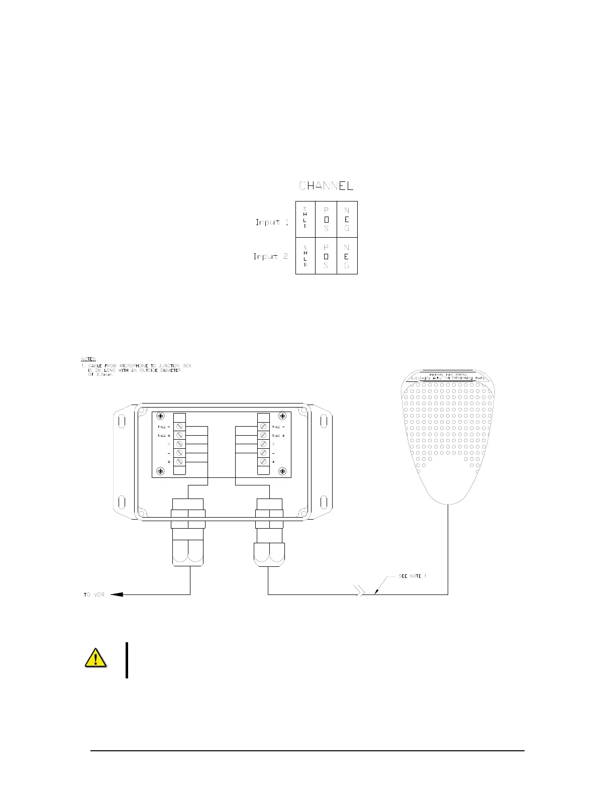
Each microphone (complete with its internal buzzer) is connected to the VDR-100G3 through its
junction box which contains wiring terminals and a microphone pre-amp:
The microphone junction box is wired to the VDR-100G3 using a two-pair shielded cable;
The microphone connects same as below in the audio junction box; and
The buzzer is connected to the terminal blocks in the audio junction box.
Figure 8-6 - Audio Module - Individual Channel Connections
8.3.1 Indoor Microphone and Buzzer
Figure 8-7 - Internal Microphone Terminal Block
Note! The conductor marked “SHD”, “S”, or “Audio Channel Shield” MUST NOT be
grounded to the internal ground bolt of the DPU.
To minimize wiring from the audio junction boxes to the VDR-100G3, it is possible to connect the
VDR-100G3 cable from all the audio junction boxes to a central junction box and run a single
VDR-100G3/G3S Installation Manual 06/10/2008
8-10