Chapter 12: Final Recording Medium Setup, Rev. 1.5
12.2.2.4 Connecting the L3 HVR/SVR Fixed FRM/SFRM Capsule Fixed SFRM
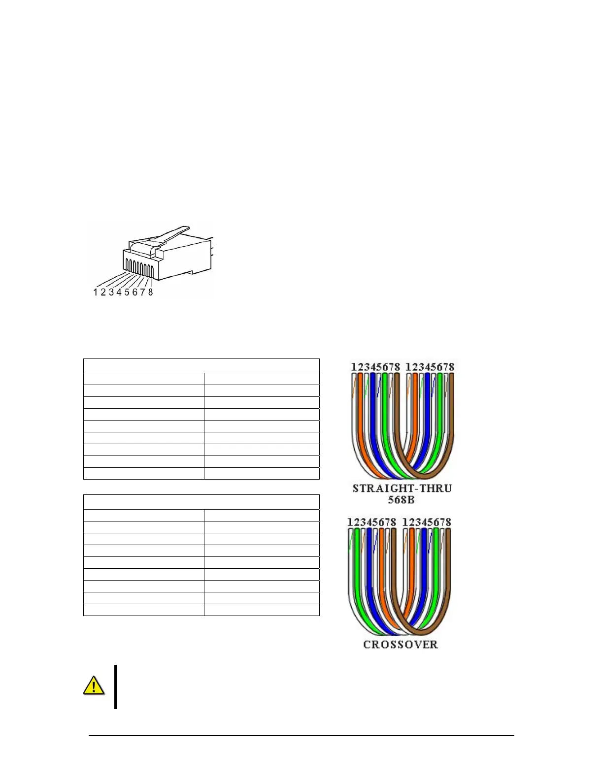
The wiring of the connections between the VDR-100G3 and the L3 HVR/SVR Fixed FRM/SFRM
Capsule is via the RJ45 connector (illustrated in Figure 12–7 - RJ45 Connector).
The junction box adjacent to the FRM/SFRM on the vessel’s outside deck is not supplied with the
VDR-100G3/S. It connects the cables provided with the FRM to the cables connecting to the
VDR-100G3/S.
This junction box can be located inside, but must be located within the cable distance of the
SFRM cables. It must also be fully screened and connected to the vessel’s hull. If mounted
outside, it must also be waterproof.
Figure 12–7 - RJ45 Connector
Rutter uses the 568B standard for all straight-thru Ethernet cables.
Rutter uses the crossover standard noted below for all cross-over Ethernet cables.
Straight through 568B
Connector 1 Connector 2
1 Tx+ white/orange 1 Tx+ white/orange
2 Tx- orange 2 Tx- orange
3 Rx+ white/green 3 Rx+ white/green
4 N/A 4 N/A
5 N/A 5 N/A
6 Rx- green 6 Rx- green
7 N/A 7 N/A
8 N/A 8 N/A
Table 12-7 Straight-through Ethernet cable set ups
Crossover
Connector 1 Connector 2
1 Tx+ white/orange 1 Tx+ white/green
2 Tx- orange 2 Tx- green
3 Rx+ white/green 3 Rx+ white/orange
4 N/A 4 N/A
5 N/A 5 N/A
6 Rx- green 6 Rx- orange
7 N/A 7 N/A
8 N/A 8 N/A
Table 12-8 – Cross-over Ethernet cable set ups
NOTE! It is highly recommended that cabling connecting the FRM/SFRM to the VDR-
100G3/S is installed through a gooseneck conduit (see Figure 12–1 - Sample VDR-
100G3S FRM Installation for a sample FRM installation.)
VDR-100G3/G3S Installation Manual 10/12/2008
12 - 13