Appendix 6: External Interface Modules, Rev. 1.1
A6.2.1.3 Back panel connection info:
Connector Description
ACOM System A Common (neg)
RXA1 System A input, Channel 1 (pos)
RXA2 System A input, Channel 2 (pos)
RXA3 System A input, Channel 3 (pos)
RXA4 System A input, Channel 4 (pos)
RXA5 System A input, Channel 5 (pos)
RXA6 System A input, Channel 6 (pos)
BCOM System B Common (neg)
RXB1 System B input, Channel 1 (pos)
RXB2 System B input, Channel 2 (pos)
RXB3 System B input, Channel 3 (pos)
RXB4 System B input, Channel 4 (pos)
RXB5 System B input, Channel 5 (pos)
RXB6 System B input, Channel 6 (pos)
CCOM System C Common (neg)
RXC1 System C input, Channel 1 (pos)
RXC2 System C input, Channel 2 (pos)
RXC3 System C input, Channel 3 (pos)
RXC4 System C input, Channel 4 (pos)
RXC5 System C input, Channel 5 (pos)
RXC6 System C input, Channel 6 (pos)
DCOM System D Common (neg)
RXD1 System D input, Channel 1 (pos)
RXD2 System D input, Channel 2 (pos)
RXD3 System D input, Channel 3 (pos)
RXD4 System D input, Channel 4 (pos)
RXD5/TX- System D input, Channel 5 (pos)
/ RS422 Data Output (neg) **
RXD6/TX+ System D input, Channel 6 (pos)
/ RS422 Data Input (pos) **
+ (12VDC) 12VDC Input power
- (12VDC) 12VDC Input power common
Table A6 - 7 - Back Panel Connection Information
Warning! Connect power to either the front OR rear of the interface. Only one
power input is required. Power connections are parallel.
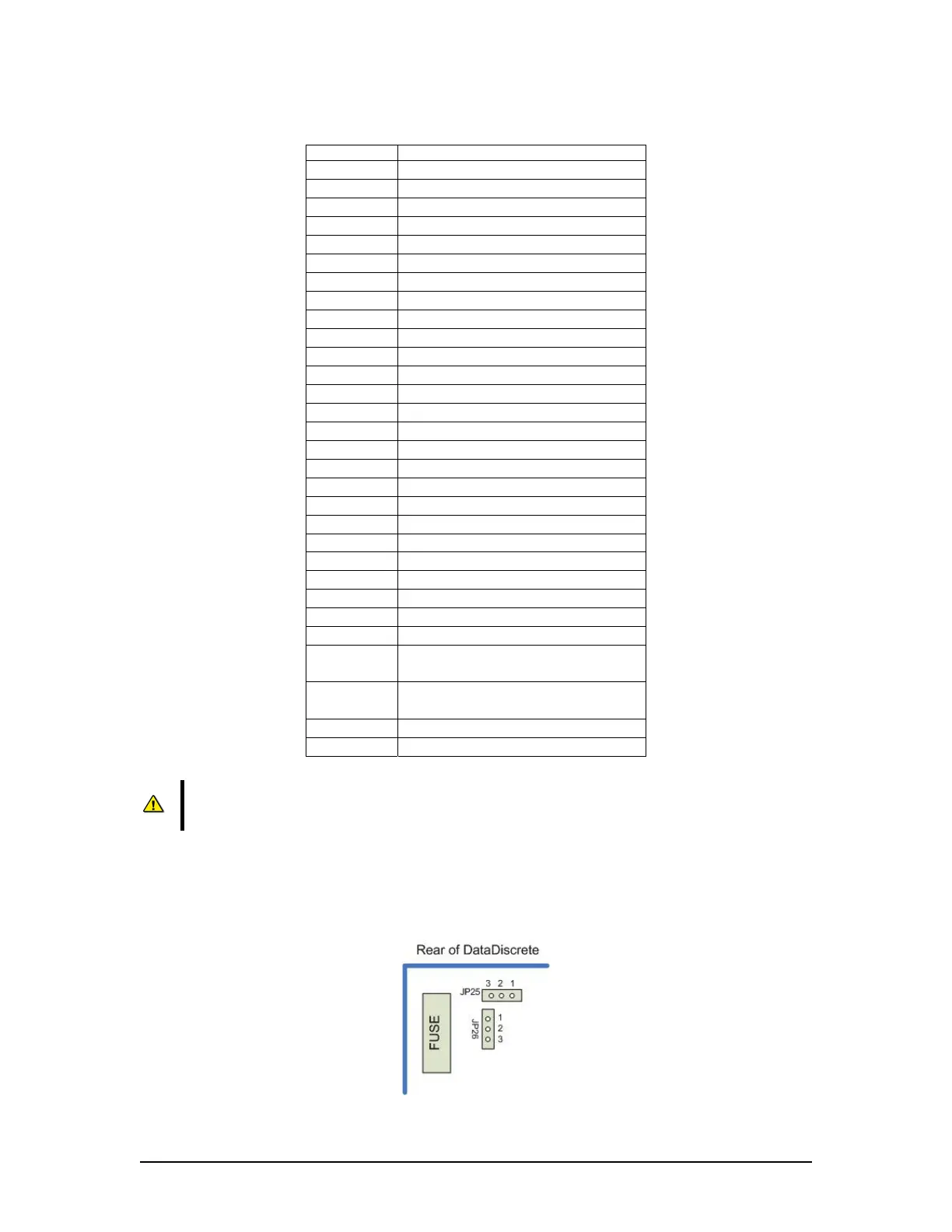
** These connection points in Table A6-7 can be used as either a discrete input channel, or
optionally, as a RS422 data output, depending on the position of jumpers JP25 and JP26 on the
circuit board. When JP25 and JP26 are in positions 1 and 2, the connectors are RXD5 and RXD6
(default setting). When JP25 and JP26 are set to positions 2 and 3, the connectors are TX- and
TX+.
Figure A6 - 5 Jumper Positions
VDR-100G3/G3S Installation Manual 06/10/2008
10