Appendix 6: External Interface Modules, Rev. 1.1
A6.2.1.5 Output Format
The format of the NMEA-0183/IEC 61162 output sentence is as follows:
$DISXX,A
1
A
2
A
3
A
4
A
5
A
6
,B
1
B
2
B
3
B
4
B
5
B
6
,C
1
C
2
C
3
C
4
C
5
C
6
,D
1
D
2
D
3
D
4
D
5
D
6
*AA
where:
XX is set between 00 to 63 (see NMEA-0183/IEC 61162 String Identifier Configuration below);
A
1-6
, B
1-6
, C
1-6
, D
1-6
indicate the status of input channels (1 for 'ON', 0 for 'OFF');
AA is the checksum.
Example: $DIS12,000100,111101,000000,001100,*F7
A6.2.1.6 Onboard DIP-Switch Settings
An 8-switch dip-switch is located on the front of the input circuit board adjacent to the power switch.
Positions 1 through 6 change the output designation number from 0 to 63 in binary format (see String Identifier
table in NMEA-0183/IEC 61162 String Identifier Configuration section below), without restarting (i.e., all 6 in the
ON position would give an output of $DIS63).
Switches 7 and 8 control the output repetition rate, as follows (Code version 09/03):
Switch 7 8
Maximum No of DataDiscrete:
Daisy-Chaining
1 Hz OFF OFF 3
1/3 Hz ON OFF 4
1/6 Hz OFF ON 5
1/10 Hz ON ON 10
Table A6 - 8 - Onboard DIP-switch settings
Changes to the output repetition rate can also be made without restarting the device.
NOTE! The above provided daisy-chain settings allow for a maximum string return.
A6.2.1.7 Discrete Input Voltage Levels
Minimum Voltage Levels (V) Maximum Voltage Levels (V)
Low Voltage Input (Jumpers ON) 3 60
High Voltage Input (Voltage OFF) (130K res 23.0 VDC) 170
AC Input (130K res 18 VDC) 120
Table A6 - 9 - Discrete Input Voltage Levels
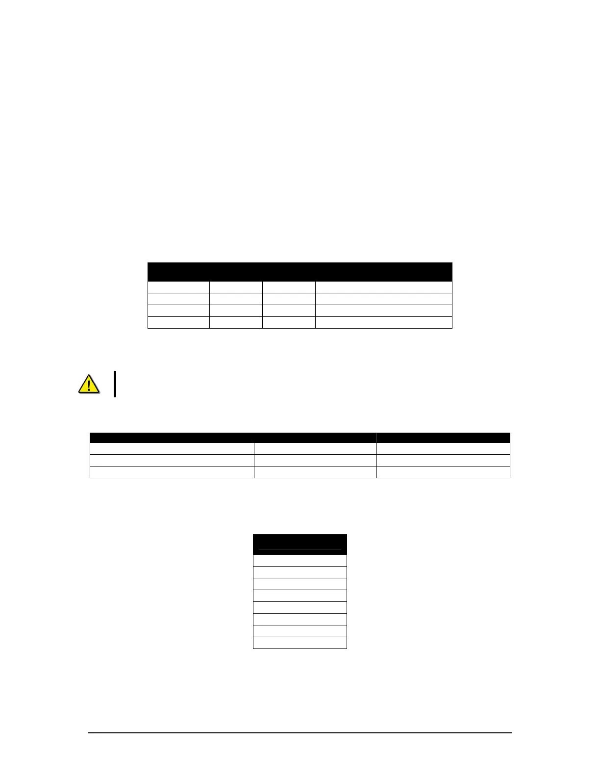
A6.2.1.8 Front 8-Pin Phoenix Connector Pin-Out
Refer to the following table for pin-out information:
Front 8-Pin Pin-Out
Pin 1 – Vin
Pin 2 – PGND
Pin 3 – TX0
Pin 4 – GND
Pin 5 – RX0
Pin 6 – RX0RET
Pin 7 – TX0-
Pin 8 – TX0+
Table A6 - 10 Front 8-Pin Phoenix Connector Pin-Out
VDR-100G3/G3S Installation Manual 06/10/2008
12