Chapter 12: Final Recording Medium Setup, Rev. 1.5
VDR-100G3/G3S Installation Manual 10/12/2008
12 - 7
Connections found in the Drawing Appendix section of the VDR-100-G3 Approval Drawing
package at the back of the VDR-100-G3 Installation Manual.
The junction box adjacent to the FRM on the vessel’s outside deck is not supplied with the VDR-
00G3/S. It connects the cables provided with the FRM to the cables connecting to the VDR-
RM cables. It must also be fully screened and connected to the vessel’s hull. If mounted outside,
ed
1
100G3/S. The J-Box is where the Ethernet Crossover connection is made.
This junction box can be located inside, but must be located within the cable distance of the
F
it must also be waterproof. Wiring of the Rutter FRM (RUT-02447) Fixed Capsule is summariz
as follows:
Rutter Fixed Capsule J-Box Wiring
DMM RJ-45 Plug
VDR Side
Terminal
Block
Number FRM Side Signal
WHITE/ORANGE 1 ORANGE BLUE Rx+ 1
OR 2 WHI E Rx- ANGE TE/ORANG 2 WHITE
WHITE/GREEN 3 GREEN 3 ORANGE Tx+
GREEN 6 WHITE/GREEN 4 YELLOW Tx-
PCC/FRM-PWR+ VDC BROWN 5 BLUE +24
PCC/FRM-PWR- HITE 6 HITE VDC RET. W W 24
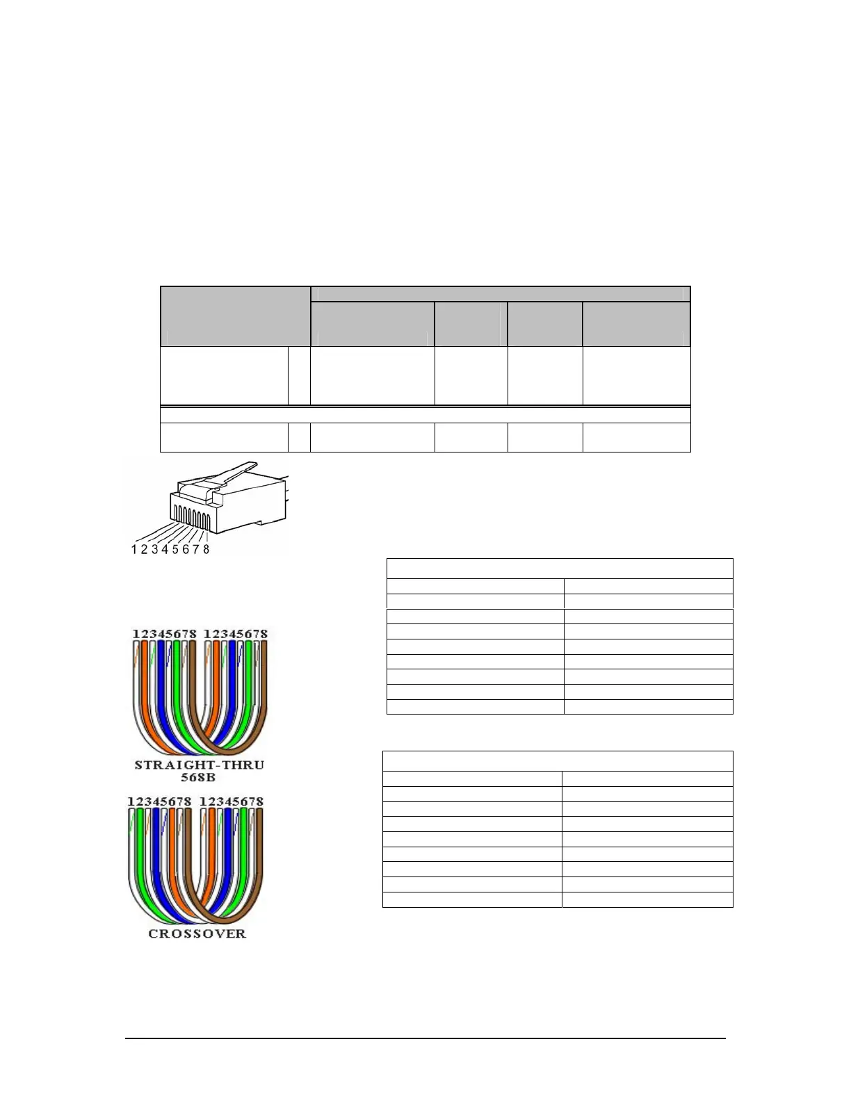
Rutter uses the 568B standard for all straight-thru Ethernet cables.
Rutter uses the crossover standard noted below for all cross-over
Figure 12–5 - RJ45 Connector
Table 12-4 Straigh Ethernet cable set ups
--
--
Ethernet cables.
t-through
Crossover
Connector 1 Connector 2
1 Tx+ white/orange white/green 1 Tx+
2 Tx- 2 Tx- orange green
3 Rx+ white/green 3 Rx+ white/orange
4 N/A 4 N/A
5 N/A 5 N/A
6 Rx- green orange 6 Rx-
7 N/A 7 N/A
8 N/A 8 N/A
Table 12-5 – Cross-over hernet cable set ups
Straight through 568B
Et
Connector 1 Connector 2
1 Tx+ white orange /orange 1 Tx+ white/
2 Tx- 2 Tx- orange orange
3 Rx+ white/green 3 Rx+ white/green
4 N/A 4 N/A
5 N/A 5 N/A
6 Rx- green green 6 Rx-
7 N/A 7 N/A
8 N/A 8 N/A