Chapter 9: Video Module, Rev. 1.2
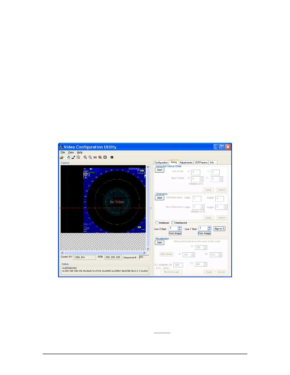
ii. Click the Start button in the Recalibration section at the bottom of the Sizing
page;
iii. In the Capture window click and drag a rectangle around the circle, OR click
the Pick Points button to select the points of the circle in order. (Picking
points may be easier.);
iv. When 4 points of the circle are selected by either method above, click the
Apply button;
v. This applies the adjusted value of the Phase Lock Loop PLL Multiplier
Number (N) and recalibrates the captured image;
vi. If the recalibrated image has improved but needs further recalibration, click
and drag a rectangle around the circle, OR click the Pick Points button to
select the points of the circle in order. (Picking points may be easier.);
vii. When 4 points of the circle have been chosen, by either method above, click
the Apply button;
viii. This will apply the newly re-adjusted value of the PLL Multiplier Number (N);
ix. If the circle in the newly recalibrated image appears more oval than in step vi,
click Start to begin again;
x. Click Revert to Last to reset to the previous value of the PLL Multiplier (N);
xi. Click Apply, and repeat this procedure from step iv.
Figure 9-20 - Correct aspect ratio after recalibration
2. The Image Offset of the captured image will need to be re-adjusted. Follow the steps
above Section 9.5.3.1: Horizontal/Vertical Offset to adjust the upper left corner of the
image.
Note: With many radar images, it may be difficult to determine the true upper left corner of the
captured image. The installer may have to adjust the image’s position a number of times to
ensure it is as close as possible to the top left corner without
losing any part of the image.
VDR-100G3/G3S Installation Manual 06/10/2008
9-19