Chapter 12: Final Recording Medium Setup, Rev. 1.5
VDR-100G3/G3S Installation Manual 10/12/2008
12 - 16
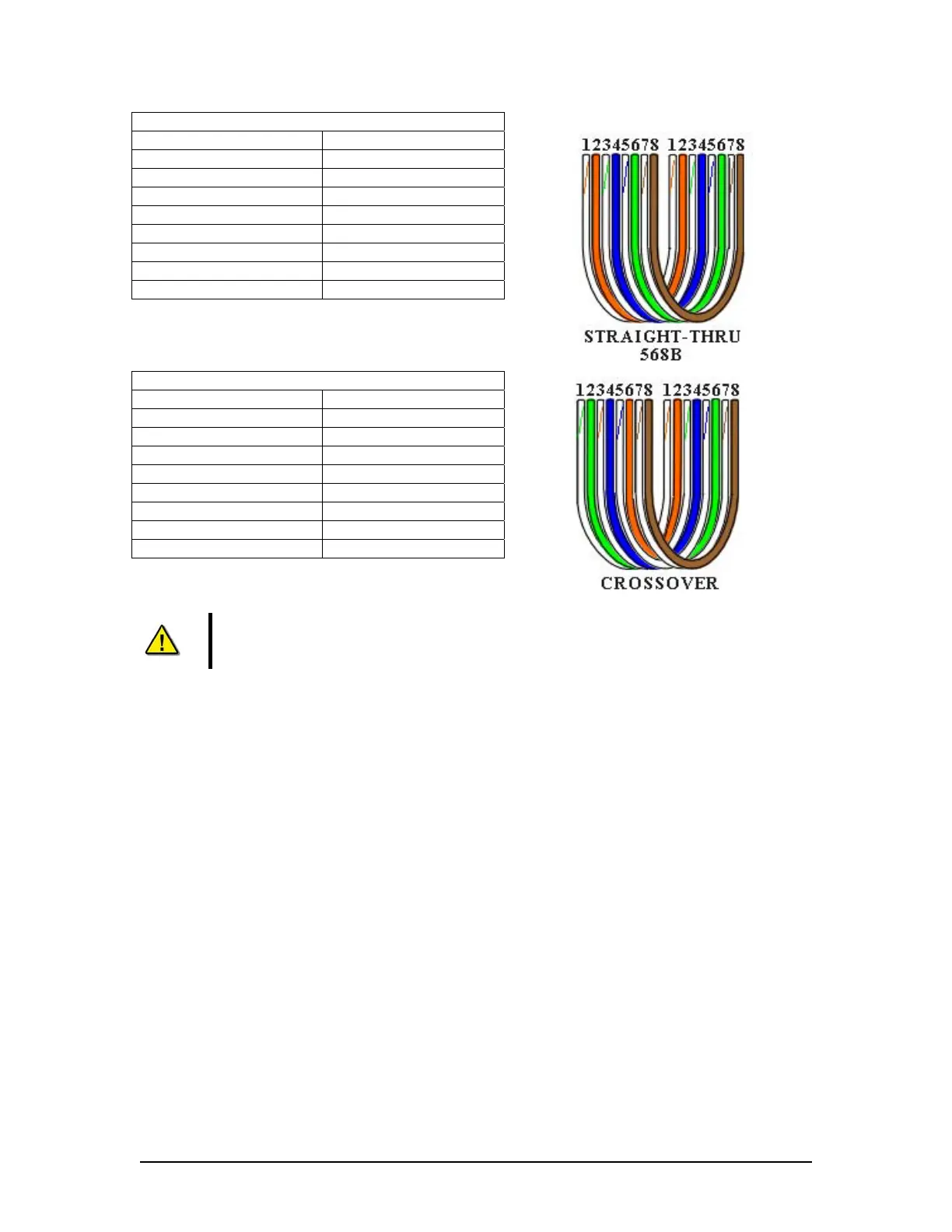
Straight through 568B
Connector 1 Connector 2
1 Tx+ white/orange 1 Tx+ white/orange
2 Tx- orange 2 Tx- orange
3 Rx+ white/green 3 Rx+ white/green
4 N/A 4 N/A
5 N/A 5 N/A
6 Rx- green 6 Rx- green
7 N/A 7 N/A
8 N/A 8 N/A
Table 12-7 Straight-through Ethernet cable set ups
Crossover
Connector 1 Connector 2
1 Tx+ white/orange 1 Tx+ white/green
2 Tx- orange 2 Tx- green
3 Rx+ white/green 3 Rx+ white/orange
4 N/A 4 N/A
5 N/A 5 N/A
6 Rx- green 6 Rx- orange
7 N/A 7 N/A
8 N/A 8 N/A
Table 12-8 – Cross-over Ethernet cable set ups
NOTE! It is highly recommended that cabling connecting the FRM/SFRM to the
VDR-100G3/S is installed through a gooseneck conduit (see Figure 12-1 - Sample
VDR-100G3S FRM Installation for a sample FRM installation.)