Appendix 2: System Configuration File, Rev. 1.1
2. Press the setup button to open a data discrete setup window.
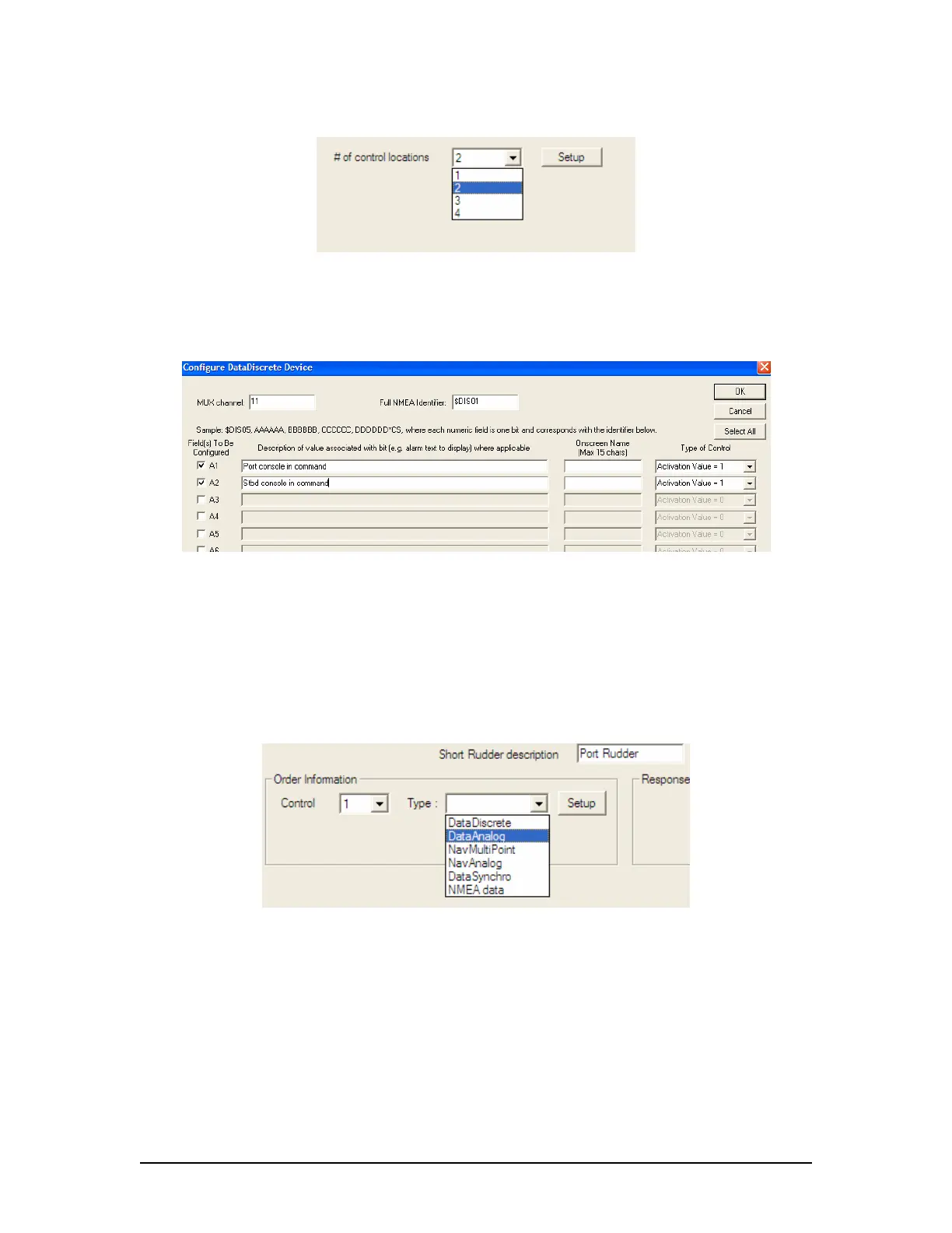
Figure A2- 35 - Control Locations – Example 1
3. In this situation the DataDiscrete is set up in the same manner as any other application
of the data discrete device. The first entry in the discrete contact list corresponds to
control location #1 by default; the second belongs with #2, and so on. The Onscreen
Name is not used in this page. Press “OK” to return to the rudder setup page.
Figure A2- 36 - DataDiscrete Configuration – Example1
4. It is now necessary to set the number of rudders. Select the number of rudders using
the available “Number of Rudders” radio buttons.
5. A number of tabs will appear corresponding to the number of rudders selected. For the
first rudder, in the “Order Information” section, select “1” from the “Control” drop down
box. Select the data source in the adjacent ‘Type’ drop down box (in most situations,
the data source will be a Data Analog device).
6. Press the “Setup” button to input the data for the Data Analog device. This setup is
standard for propulsion, rudder, and thruster data provided by a Data Analog device.
Figure A2- 37 - Control Type – Example1
7. When the ‘Configure a DataAnalog Device’ window appears, the Mux channel and
NMEA Identifier should be specified as shown below. The field in which the data
appears must also be specified.
8. Once this data field has been selected, pressing the “Configure Data Points” button will
open an additional window that allows the installation technician to specify what values
on the DataAnalog correspond to exact rudder positions. In each case, it is important to
specify the extreme range of the rudder and also include the midship or ‘0’ position.
9. Once all the rudder position data has been entered for rudder # 1 order, select “Control
Location” number “2” from the Order Information box and repeat the above steps to
enter all pertinent order information for the second (STBD) control station.
VDR-100G3/G3S Installation Manual 06/10/2008
38