Chapter 8: Audio Module, Rev 1.1
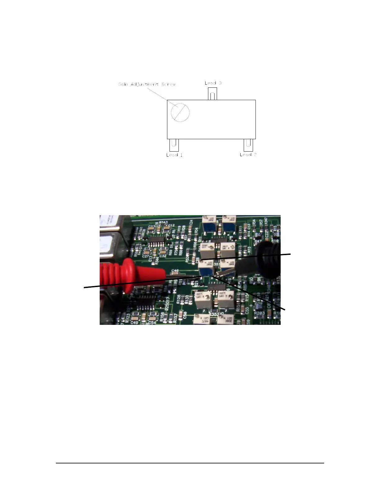
5. Adjust the potentiometer gain using the Gain adjustment screw on the potentiometer for
the desired resistance. Refer to Table 8.6: Recommended Resistance Readings. The
higher the resistance the higher the gain (This increases or decreases the audio input
level). Turn the Gain adjustment screw clockwise to increase the gain.
Figure 8-15 – Potentiometer Leads
Note! There are 3 leads for each potentiometer. Only 2 of these leads are used to
measure a resistance reading.
Lead Two
Gain Adjustment
Screw
Lead One
Figure 8-16 - Potentiometer Lead Resistance Reading
VDR-100G3/G3S Installation Manual 06/10/2008
8-19