PROGRAMMING GUIDE
SINUS PENTA
135/486
19. SPEED LOOP AND CURRENT BALANCING MENU
19.1. Overview
The SPEED LOOP AND CURRENT BALANCING MENU, for VTC and FOC controls, allows setting the parameter
values of the speed regulators for the three connected motors and to manually adjust the motor current balancing (see
parameter P152).
The speed regulator for each motor has two parameterization functions: two integral terms and two proportional terms.
As per factory settings, only parameters P126 (Maximum Integral Time) and P128 (Minimum Integral Time) are used.
Adopting the remaining two parameters P125 (Minimum Integral Time) and P129 (Maximum Proportional Constant) is
based on two possible control logics:
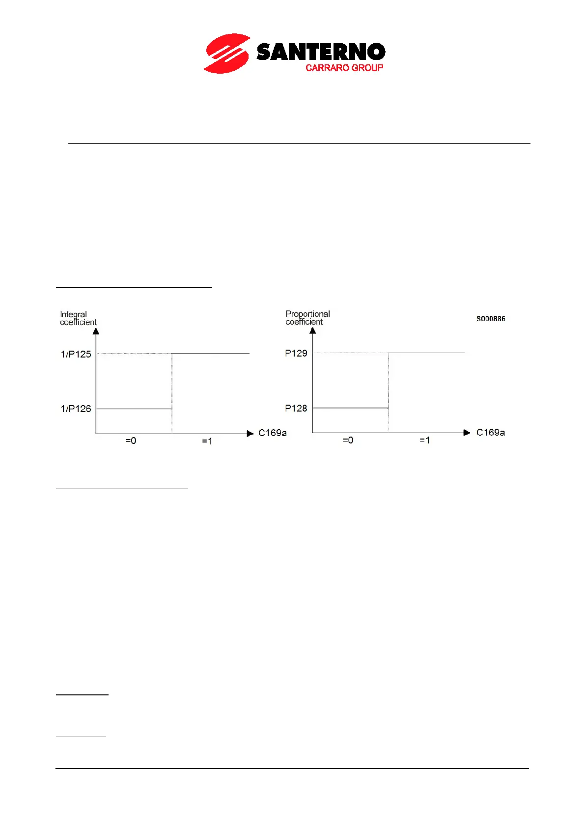
• Status of the digital input set in C169a (FOC control only);
• Logics based on the adjustment error.
Status of the digital input set in C169a: if the input is low, parameters P126/P128 will be active; otherwise (high logic
level) parameters P125/P129 will be active.
Figure 14: Example of dual parameterization activated by a digital input
Logic based on adjustment error: This second logic enables a regulator’s response dynamically related to the speed
error; in that way, the speed regulator will be more reactive to big errors and less sensitive to small errors. To activate
this control logics, speed error thresholds P130 and P131 (expressed as a percentage of the rated speed) are to be set
to different values.
The response of the speed regulator can be dynamically linked with the speed error; in this way, the speed regulator will
be more sensitive to remarkable speed errors and less sensitive to negligible speed errors.
Factory setting: because two identical error thresholds are set, only two parameters are used: P126 (maximum integral
time) and P128 (minimum proportional constant).
The setup of min. integral time and max. proportional constant is enabled provided that two different error thresholds are
used.
Example:
Minimum proportional constant
Maximum proportional constant
Error ≤ P130
For speed errors lower than or equal to 2% of the motor rated speed, the speed regulator adopts parameters P126 and
P128.
Error ≥ P131
If the speed error is higher than or equal to 20% of the rated motor speed, the speed regulator adopts parameters P125
and P129.