PROGRAMMING GUIDE
SINUS PENTA
187/486
26. DIGITAL OUTPUTS MENU
26.1. Overview
The Digital Outputs menu includes the parameters allowing configuring the drive digital outputs (MDO1, MDO2, MDO3
and MDO4).
NOTE
Relay digital output MDO4 is allocated to the Safe Torque Off (STO) function and cannot
be configured by the user.
The MDO4 digital output may be configured only after deactivating the Safe Torque Off
function (please refer to the Sinus Penta’s Installation Guide).
NOTE
The Digital Outputs menu may be accessed only if the user level is ADVANCED or
ENGINEERING.
NOTE
For a detailed hardware description of the digital outputs, please refer to the Sinus
Penta’s Installation Guide.
NOTE
MDO1 digital output can be programmed only if the frequency output is not set up (P200
= Disable; see the ANALOG AND FREQUENCY OUTPUTS MENU).
NOTE
XMDI digital outputs (values from 13 to 20 in the
parameters relating to the control
functions) can be set up only after setting XMDI/O in parameter R023.
26.1.1. FACTORY SETTINGS
The factory settings are as follows:
MDO1 is a zero speed relay (it energizes when a preset threshold is exceeded).
MDO2 controls an electromechanical brake used for crane applications (it energizes to release the brake).
MDO3 de-energizes (fail-safe logic) in case of “Inverter Alarm”.
MDO4 energizes when the drive is running and is enabling the power stage (“Inverter Run OK” condition).
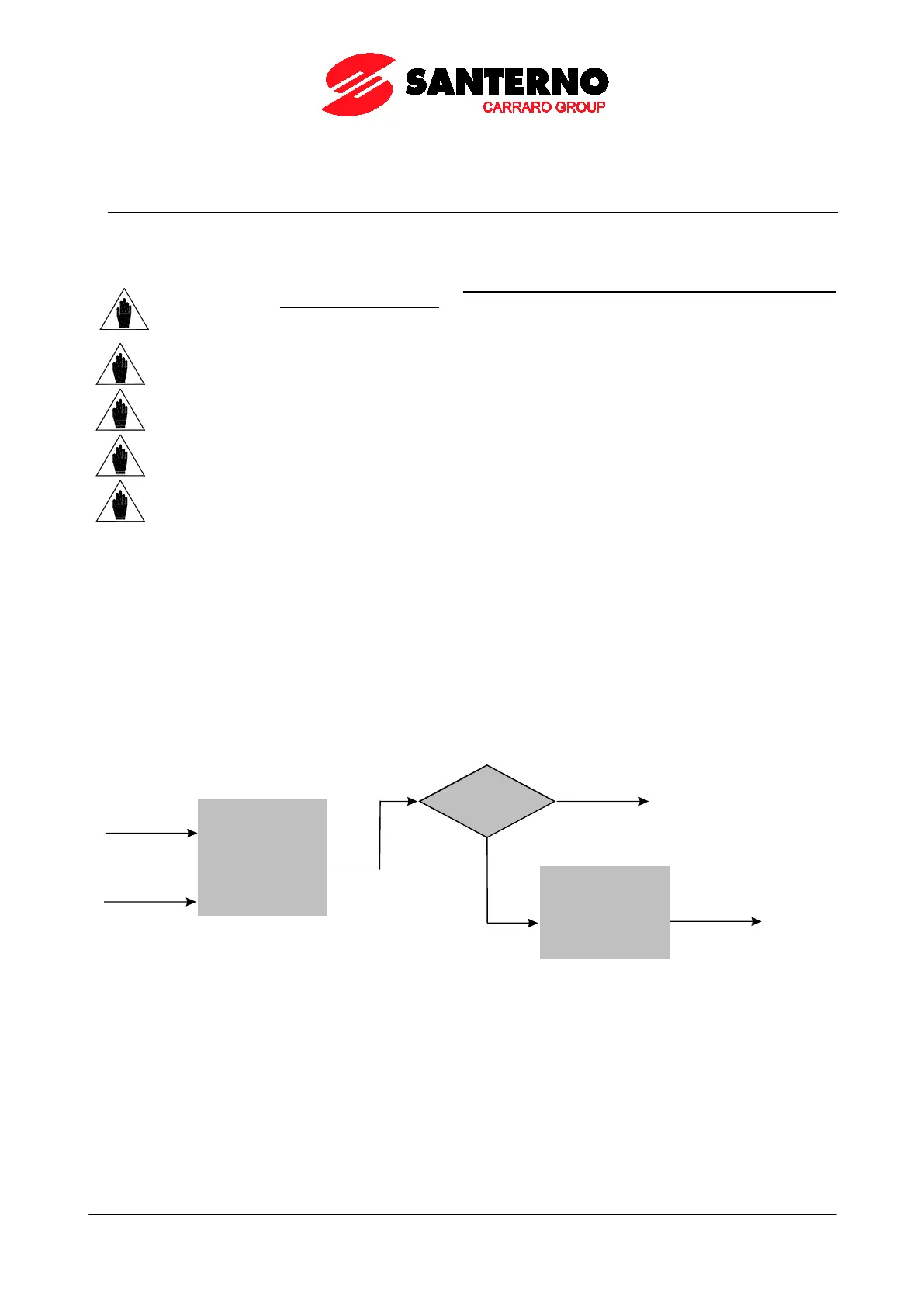
26.1.2. STRUCTURE OF THE DIGITAL OUTPUTS
A digital output is composed of two logic blocks allowing data processing before actuating the actual digital output.
Block 2 depends on the settings in parameters P277a (P286a, P295a, P304a).
Logic Block
set b y
parameters
P271-P277
IN PUT A
IN PUT B
f(A, B)
P277a = 0
yes
Output= f
(A, B)
NO
Logic block
set by P277b
tha t tests f(A,B)
and signal C
Output=
g [f(A,B), C ]
P000659-b
Figure 32: MDO block-diagram