SINUS PENTA
PROGRAMMING GUIDE
148/486
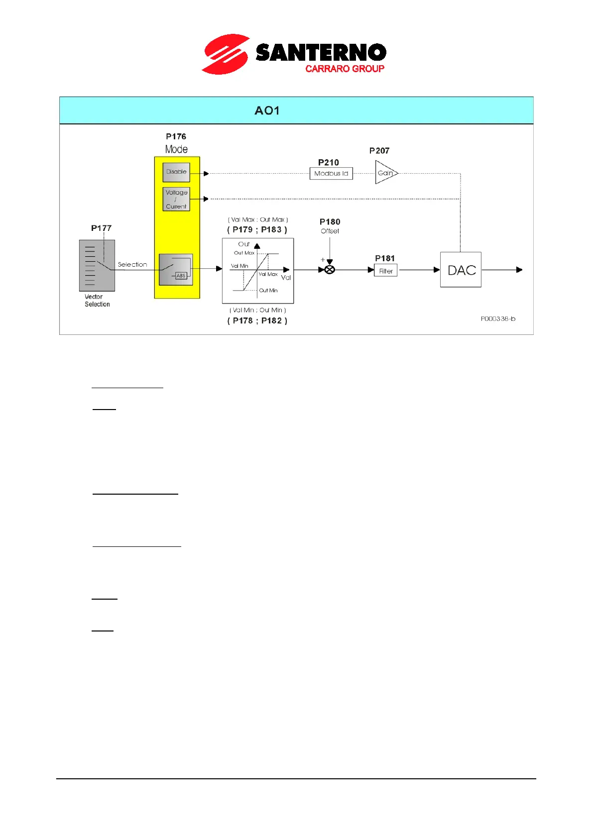
Figure 16: Typical structure of the Analog Outputs
• Vector Selection Selects the variable to be represented through the digital analog converter (DAC). P177 is
the selection parameter for AO1analog output and P185 and P193 for AO2 and AO3 respectively.
• Mode Sets the acquisition mode of the selected variable (± or as an absolute value) and the type
(voltage/current) for the analog output. If Mode = Disable, a different operating mode is activated for the analog
output for which the represented variable is determined by the MODBUS address set in Address and the gain
value set in Gain is applied:
P176 (Mode), P207 (Gain), P210 (Address) for AO1;
P184 (Mode), P208 (Gain), P211 (Address) for AO2;
P192 (Mode), P209 (Gain), P212 (Address) for AO3.
• (Val Min; Out Min) Defines the minimum saturation value of the variable to be represented and the
corresponding value to be assigned to the analog output. For values equal to or lower than Val Min, Out Min
will be assigned to the selected analog output. For analog outputs AO1, AO2, and AO3, the following
parameters will be used: (P178; P182), (P186; P190) and (P194; P198) for values (Val Min; Out Min).
• (Val Max; Out Max) Defines the maximum saturation value of the variable to be represented and the
corresponding value to be assigned to the analog output. For values equal to or higher than Val Max, Out Max
will be assigned to the selected analog output. For analog outputs AO1, AO2, and AO3, the following
parameters will be used: (P179; P183), (P187; P191) and (P195; P199) for values (Val Max; Out Max).
• Offset Defines the offset value applied to the analog output. Offset is set in parameter P180 for AO1 analog
output, in parameters P188, P196 for AO2 and AO3 respectively.
• Filter Defines the filter time constant applied to the analog output. The filter time constant is set in parameter
P181 for AO1 analog output, in parameters P189, P197 for AO2 and AO3 respectively.