PROGRAMMING GUIDE
SINUS PENTA
153/486
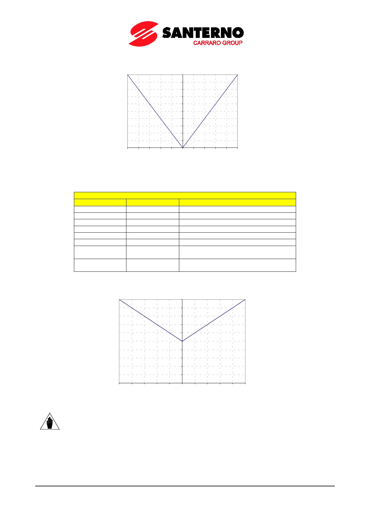
Figure 19: Curve (voltage; speed) implemented by AO1 (Example 2)
0
1
2
3
4
5
6
7
8
9
10
-500 -400
-300 -200
-100
0 100
200 300
400
500
Example 3:
Table 39: Programming AO1 (ABS 0 ÷ 10V)
Parameterization of Analog Output AO1
Selected variable for AO1 analog output
Min. value of AO1 selected variable
Max. value of AO1 selected variable
Filter for AO1 analog output
P182 0.0 V
Min. AO1 output value with reference to
P178
P183 10.0 V
Max. AO1 output value with reference to
P179
Figure 20: Curve (voltage; speed) implemented by AO1 (Example 3)
0
1
2
3
4
5
6
7
8
9
10
-500 -400 -300 -200 -100 0 100 200 300 400 500
NOTE
The programming mode above would imply a straight line passing through (–500rpm; 0V)
and (+500rpm; 10V), but based on the selected mode and considering the variable as an
absolute value, the min. point for output AO1 will be (0 rpm; 5 V).