PROGRAMMING GUIDE
SINUS PENTA
201/486
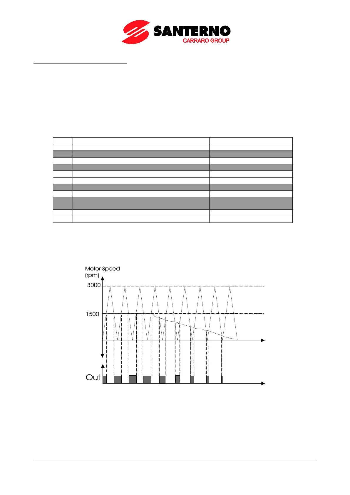
Example 5: Using the PWM Function.
Suppose that the motor of a machine tool is controlled by a drive. The tool must be lubricated based on the cutting
speed. At max. cutting speed, the electrovalve controlling lubrication must work for 0.5 sec with a frequency of 1Hz (time
period of 1 sec.): at max. speed, a duty cycle of 50% (Ton/T) is required, with a time period of 1 second; the time when
the electrovalve opens is directly proportional to the cutting speed.
Spd1 is the max. cutting speed and dtc1 is the duty cycle required; the saw carrier frequency required for PWM must be
1 Hz (P213), the min. value must be 0rpm (when speed = 0rpm, the electrovalve is disabled) and max. value =
Spd1*100/ dtc1 = 2*Spd1.
Supposing that the tool can rotate in both directions, that Spd1 = 1500rpm and that the first digital output is used,
parameters are set as follows:
Table 54: MDO parameterization for the PWM function
MDO1: Digital output mode
MDO1: Variable A selection
MDO1: Variable B selection
MDO1: Comparing value for Test A
MDO1: Comparing value for Test B
MDO1: Function applied to the result of the two tests
MDO1: Variable C selection
MDO1: Function applied to the result of f(A,B) and C
test
Parameter P215 in the ANALOG AND FREQUENCY OUTPUTS MENU sets the frequency of the saw wave, i.e. the
PWM frequency of the digital output.
In PWM mode, parameter P275 sets the max. value (peak value) of the saw wave, while parameter P276 sets the min.
value of the saw wave.
The test selected with P273 is performed between the analog variable selected in P271 and the saw wave.