SINUS PENTA
PROGRAMMING GUIDE
396/486
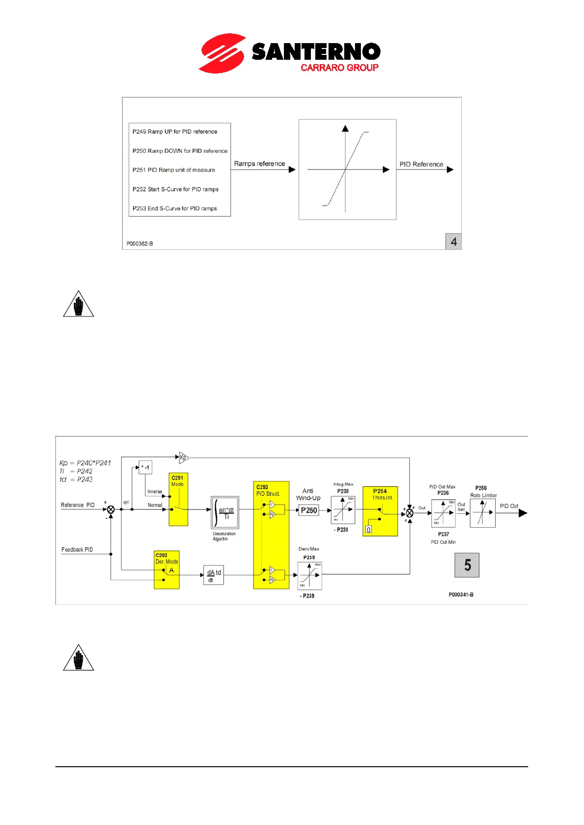
Figure 71: PID ramp reference
NOTE
The PID2 ramp reference control is the same, but parameters P2xx
parameters P4xx.
Block 5: PID regulators
This is the real PID regulator. Its output may be disabled by an external digital command (if programmed with C171). If
the PID regulator is used as a reference source and P255 (P455 for PID2) is not set to zero, the PID output value
control is enabled. If the PID output equals the preset minimum value for a time longer than P255 (P455 for PID2), the
drive is automatically put on stand-by.
In the last block, the PID output is applied to the function defined by the “PID Action” parameter (C294).
The PID regulator structure is detailed in the diagram below (block 5).
Figure 72: Details of the PID regulator structure
NOTE
The PID2 structure is the same as the PID structure, but parameters P2xx
P4xx and parameter C291 is replaced with parameter C291b. Parameters C292 and C293
are in common for PID and PID2.
Block 6: Digital input for PID control selection.
Block 6 activates only when both PIDs are enabled (C291a = 2 PID) or when in 2-Zone mode (C291a = 2-Zone MIN or
2-Zone MAX).