SINUS PENTA
PROGRAMMING GUIDE
26/486
2. DESCRIPTION OF INPUT AND OUTPUT SIGNALS
The control board of the drives of the Sinus Penta series is provided with the following inputs/outputs:
• 3 Analog Inputs (single-ended REF input, differential AIN1 & AIN2 inputs) that can be programmed as
voltage/current inputs via SW1 DIP-switch (see Configuration DIP-switches in the Sinus Penta’s Installation
Guide).
• 3 Analog Inputs that can be programmed as voltage/current inputs via SW2 DIP-switch (see Configuration DIP-
switches in the Sinus Penta’s Installation Guide).
• 8 MDI Multifunction Digital Inputs; 3 of them (MDI6, MDI7, MDI8) are fast-acquisition inputs allowing acquiring
frequency signal or encoder signals.
• MDI6 can be used to acquire a frequency signal called FINA; if used in conjunction with MDI7, it also allows
acquiring a push-pull encoder signal called Encoder A.
• MDI8 can be used to acquire a frequency input called FINB (this avoids acquiring encoder B via ES836 or ES913
optional board).
• 4 MDO Multifunction Digital Outputs; MDO1 is a Push-pull output, MDO2 is an Open Collector output and
MDO3-4 are relay outputs.
NOTE
Relay digital output MDO4 is allocated to the Safe Torque Off (STO)
configured by the user.
Electrical ratings of the control board inputs/outputs are given in the Sinus Penta’s Installation Guide.
When programming:
• Analog Inputs, see the INPUTS FOR REFERENCES MENU
• Analog Outputs, see the ANALOG AND FREQUENCY OUTPUTS MENU
• Digital Inputs, see the DIGITAL INPUTS MENU
• Digital Inputs used as Frequency/Encoder Inputs, see the ENCODER/FREQUENCY INPUTS MENU
• Multifunction Digital Outputs, see the DIGITAL OUTPUTS MENU
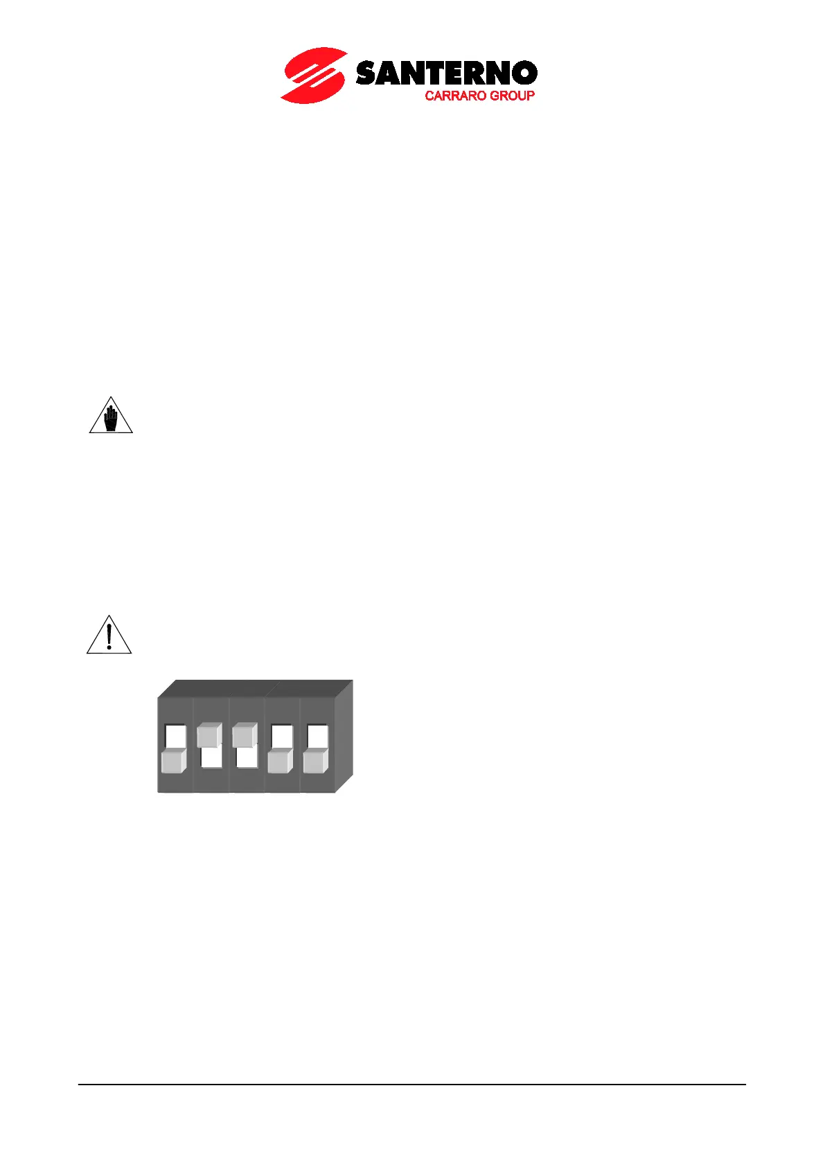
CAUTION
The drive is factory-set with the REF input configured as 0-10V and AIN1-
configured as 4-20mA.
SW1 dip-switches, which are located on the control board, must be set as follows:
SW1