PROGRAMMING GUIDE
SINUS PENTA
437/486
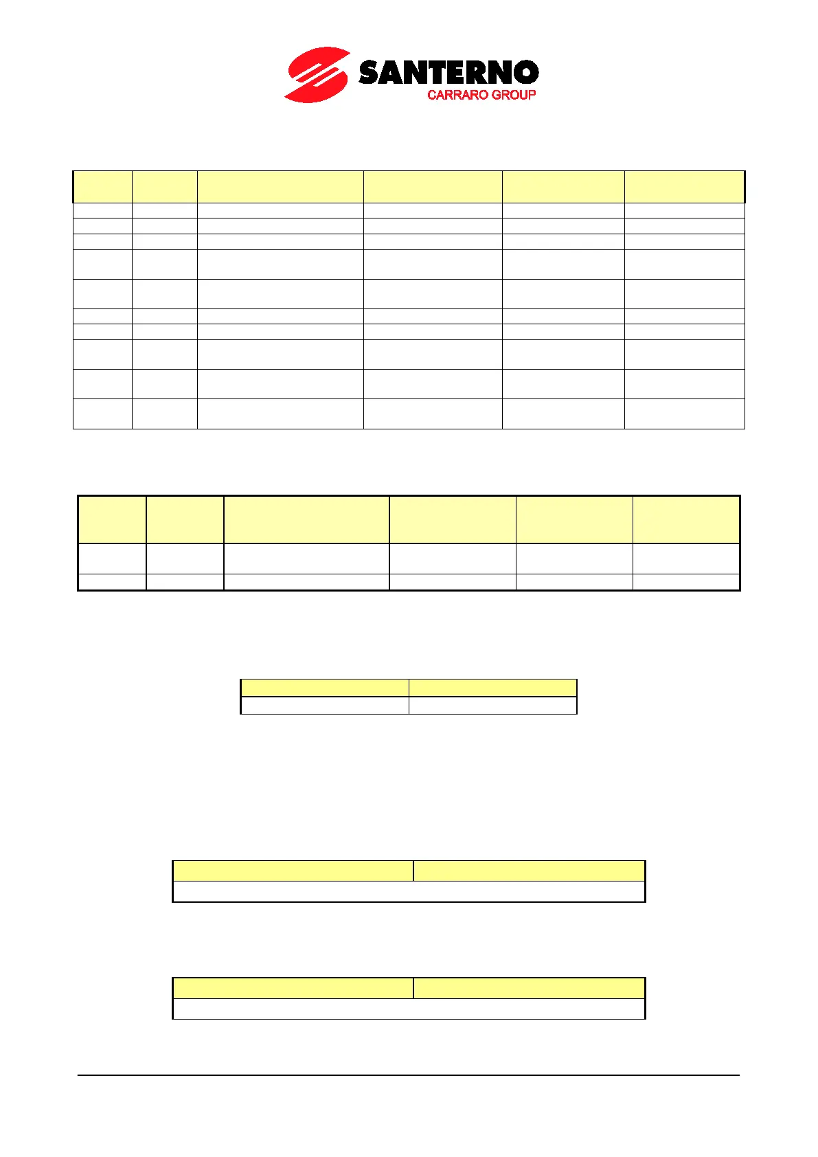
52.3.2. FROM THE SINUS PENTA TO THE MASTER
Word 1) Code 2) Description 3) Range 4) Unit of Measure 5) Scaling
4 –
Third measure that may be
configured with P330
All the measurements
5 –
Fourth measure that may be
configured with P331
All the measurements
8 REF
REF Analog Input
(default 0÷10V)
0 ÷ 15366
– –
9 AIN1
AIN1Analog Input
(default 4÷20mA)
1529..7652 – –
10 AIN2
AIN2 Analog Input
(default 4÷20mA)
1529..7652 – –
The words below are significant only when using the parameter exchange memory zone to read and write all the Penta
drive’s parameters by referring to their Modbus address.
Word 1) Code 2) Description 3) Range
4) Unit of
Measure
5) Scaling
11
Return value of the cycle
required
– – 1
Word 1: Status + Alarms
The Status and Alarms are displayed over the fieldbus in the following format:
The Status codes are given in Table 139
The Alarm codes are given in Table 136.
Word 2: Output Current
The output current measure (M026) is displayed as a value that must be divided by 10 to obtain the actual
motor current.
bit [15..8] bit [7..0]
Output Current x 10
Word 3: Motor Speed
The output motor speed (M004) is displayed as follows:
bit [15..8] bit [7..0]
Motor Speed