SINUS PENTA
PROGRAMMING GUIDE
438/486
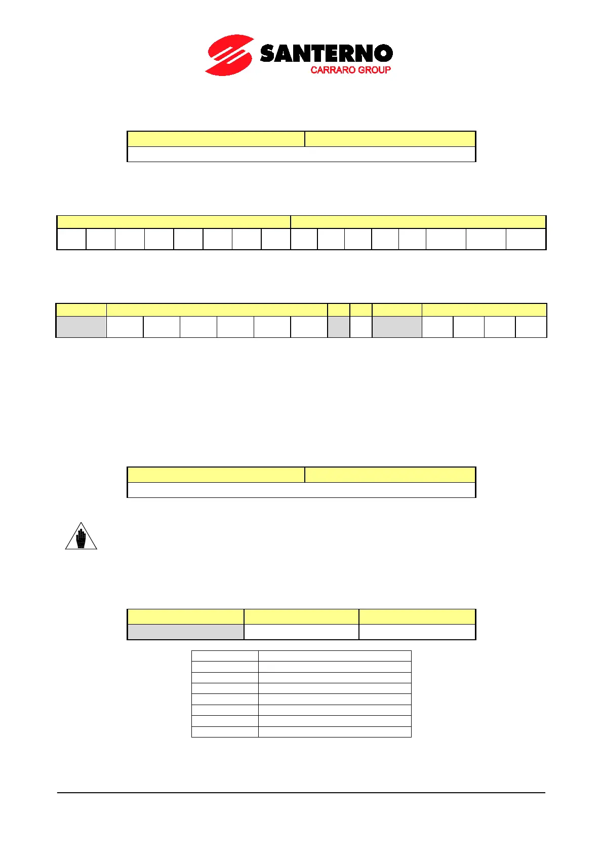
Words 4 & 5: Third & Fourth measure that may be configured with P330 & P331
Words 4 & 5 may be configured with P330 and P331 – more details are given in the FIELDBUS PARAMETERS MENU.
Both words 4 & 5 are represented as follows:
bit [15..8] bit [7..0]
Mxxx represented by P330 and P331
Word 6: Digital Inputs
Digital input status in the word:
XMDI8
XMDI4
XMDI3
MDI8
MDI7
MDI6
MDI5
MDI4
MDI2 MDI1
Word 7: Digital Outputs
Digital output status in the word:
XMDO6
XMDO5
XMDO4
XMDO3
XMDO2
XMDO1
[*] MDO4
MDO3
MDO2
[*] Status of the Pre-charge contactor
Words 8, 9, 10: REF, AIN1, AIN2 Analogue Signal
Full scale values
• 0 ÷ 15366 (0 ÷10V input)
• –15366 ÷ 15366 (± 10V input)
• 1529 ÷ 7652 (4..20mA input)
are nominal values.
These values can be changed due to automatic compensation of the tolerance of the input stage.
bit [15..8] bit [7..0]
REF / AIN1 / AIN2
NOTE
The measures of the analog inputs sent from the Sinus Penta to the Master are the
unfiltered measure values detected in the A/D converter output.
For filtered measures, use M037, M038 and M039 respectively.
Word 11: Return value of the cycle required
The word includes the return value of the cycle required (bits):
bit [15..8] bit 7 bit [6..0]
1= active cycle See table below
Word 12: Read value
The word includes the value read in case of Read cycle.
This value is to considered as legal when Word 11= 0x82 (active cycle + ANSWER OK).