PROGRAMMING GUIDE
SINUS PENTA
151/486
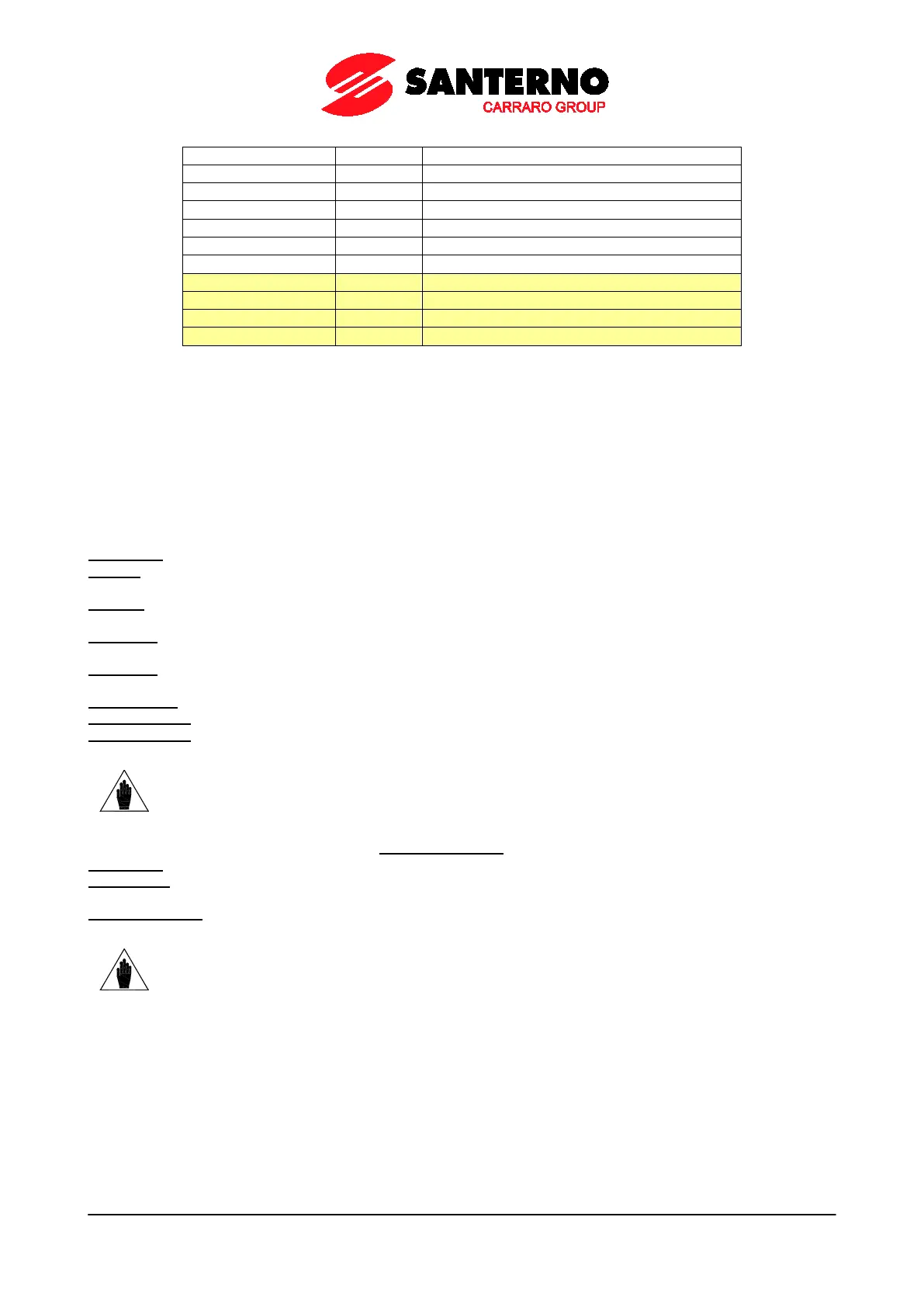
Reference at constant speed of PID2
“Ramped” reference of PID2
Error between reference and feedback of PID2
Torque demand (value percent)
Table 36 provides a brief description of each variable and its full-scale value used to set the minimum and maximum
value.
22.2.1. OPERATING MODE OF ANALOG AND FREQUENCY
OUTPUTS
This section covers the different representation modes to be selected for the analog and frequency outputs.
The following modes can be used for analog outputs:
0: Disabled Disabled analog output (enables a RESERVED operating mode).
1: ± 10V The analog output is set as a voltage output and the possible min. and max. output values range from
+/ – 10V. The selected variable has a positive or negative sign.
2: 0÷10V The analog output is set as a voltage output and the possible min. and max. output values range from
0 to 10V. The selected variable has a positive or negative sign.
3: 0÷20mA The analog output is set as a current output and the possible min. and max. output values range from
0 to 20mA. The selected variable has a positive or negative sign.
4: 4÷20mA The analog output is set as a current output and the possible min. and max. output values range from
4 to 20mA. The selected variable has a positive or negative sign.
5: ABS 0÷10V As 0÷10V output mode, but the selected variable is considered as an absolute value.
6: ABS 0÷20mA As 0÷20mA output mode, but the selected variable is considered as an absolute value.
7: ABS 4÷20mA As 4÷20mA output mode, but the selected variable is considered as an absolute value.
NOTE
Always check the min. and max. values of the outputs programmed in the relevant
parameters.
Three operating modes can be selected for the Frequency Output:
0: Disabled The output frequency is disabled.
1: Pulse Out MDO1 Digital Output is programmed as a frequency output. The selected variable has a positive or
negative sign.
2: ABS Pulse Out As Pulse Out, but the selected variable is considered as an absolute value.
NOTE
When P200
is not set to DISABLE, MDO1digital output is used as a frequency output
and any MDO1 settings in the DIGITAL OUTPUTS MENU are ignored.