PROGRAMMING GUIDE
SINUS PENTA
331/486
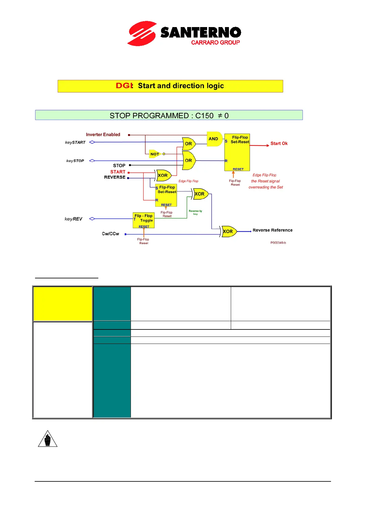
The figure below illustrates the processing logic diagram for the START, REV, Cw/CCw functions and the START,
STOP, REV keys on the display/keypad, if the STOP function is programmed.
Figure 54: Controlling Run and Direction when the STOP Input is programmed
C152 ENABLE-SW Input
C152 Range
0 ÷ 16
0 ÷ 24 if ES847 or ES870 if fitted
1 ÷ 8 → MDI1 ÷ MDI8
9 ÷ 12 → MPL1 ÷ MPL4
13 ÷ 16 → TFL1 ÷ TFL4
Function
This is an additional software-controlled Enable signal which is estimated in
series to the ENABLE function associated to MDI2 inputs.
enabled, the drive is enabled if and only if the ENABLE-A, ENABLE-B and
ENABLE-SW inputs are simultaneously activated.
If the ENABLE-SW function is programmed (C152≠0),
enable the drive:
• activate the ENABLE-SW signal
• activate the ENABLE-A and ENABLE-B signals
• activate MDI2 inputs via serial link and field
selected via C140, C141, C142.
• activate the DISABLE signal if programmed via C153.
NOTE
The ENABLE-SW signal may not delayed by the timers:
if a timer is programmed to the
terminal related to the ENABLE-SW signal, this will not affect the ENABLE-SW function,
while it normally delays other functions set to the same terminal.