PROGRAMMING GUIDE
SINUS PENTA
217/486
27. AUXILIARY DIGITAL OUTPUTS MENU
27.1. Overview
This menu includes the parameters allowing allocating the control functions implemented via the digital inputs located
on I/O expansion boards. This menu can be viewed only after enabling data acquisition from the expansion boards.
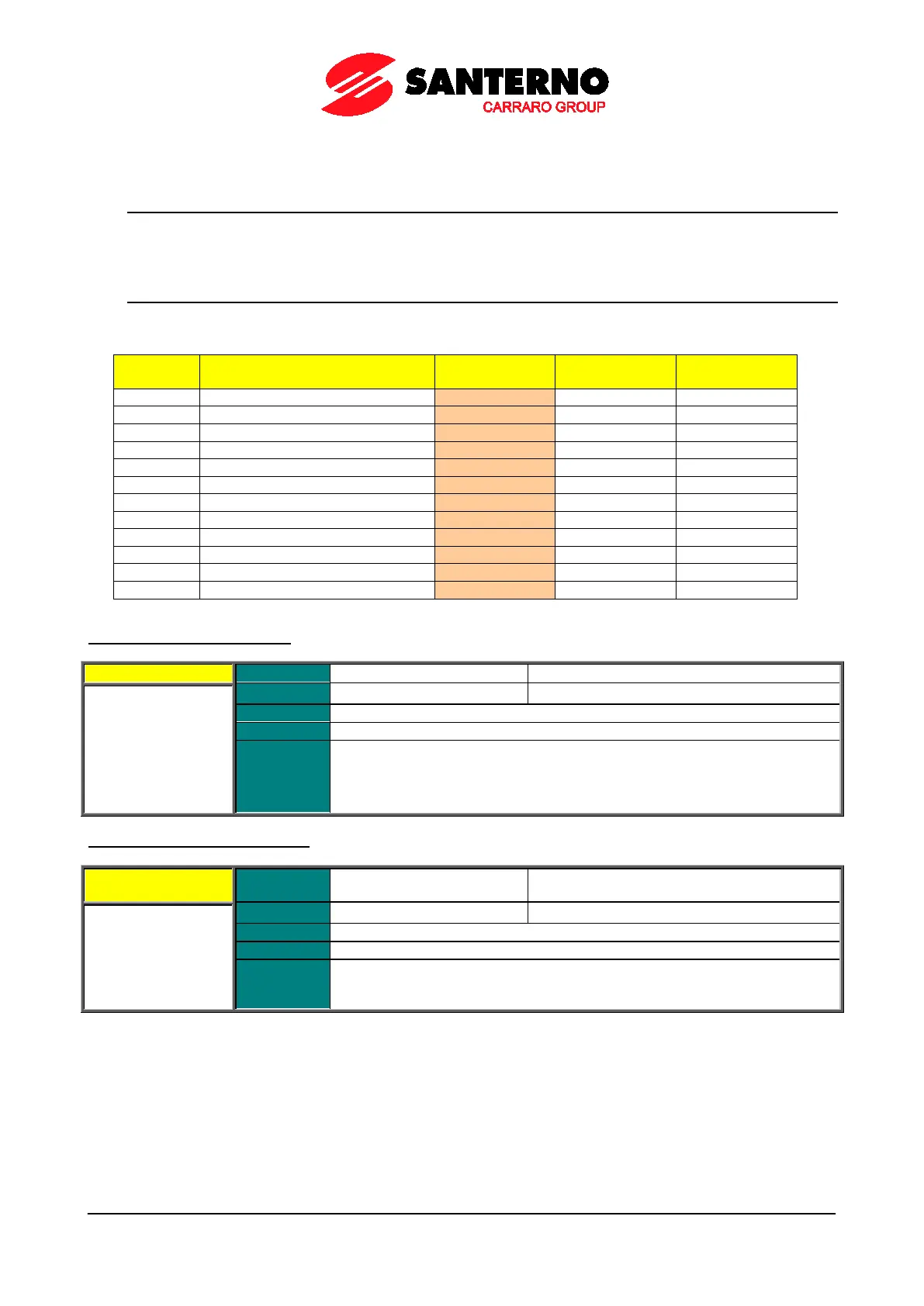
27.2. List of Parameters P306 to P317
Table 57: List of parameters P306 to P317
Parameter FUNCTION User Level
XMDO1: Output logic level
XMDO2: Output logic level
XMDO3: Output logic level
XMDO4: Output logic level
XMDO5: Output logic level
XMDO6: Output logic level
P306 XMDO1: Signal Selection
Function
Selects the digital signal used to calculate the value of XMDO1 digital output.
It selects an analog variable used to calculate the value of XMDO1
one of the “analog” operating modes is selected.
Digital signals and analog variables are detailed in Table 48.
P307 XMDO1: Output Logic Level
P307 Range
0–1
Function
XMDO1 digital output logic function to apply a logic reversal (negation) to the
calculated output signal: (0) FALSE = a logic
negation is applied; (1) TRUE = no
negation is applied.