SINUS PENTA
PROGRAMMING GUIDE
226/486
30. VIRTUAL DIGITAL OUTPUTS (MPL) MENU
30.1. Overview
The Virtual Digital Outputs menu includes the parameters allowing configuring the virtual digital outputs (MPL1..4) of the
Sinus Penta drive.
Virtual digital outputs are logic blocks (no hardware output is provided) allocating more complex logic functions to
outputs MDO1..4: MPL virtual outputs can be feedbacked at the input of a new block (hardware or virtual block), thus
allowing implementing more complex functionality.
NOTE
The Virtual Digital Outputs menu may be accessed only if the user level is ADVANCED or
ENGINEERING.
NOTE
XMDI auxiliary digital outputs (values from 13 to 20 in the parameters relating to the control
functions) can be set up only after setting XMDI/O in parameter R023.
30.1.1. FACTORY SETTING
The four virtual digital outputs are disabled as a factory setting.
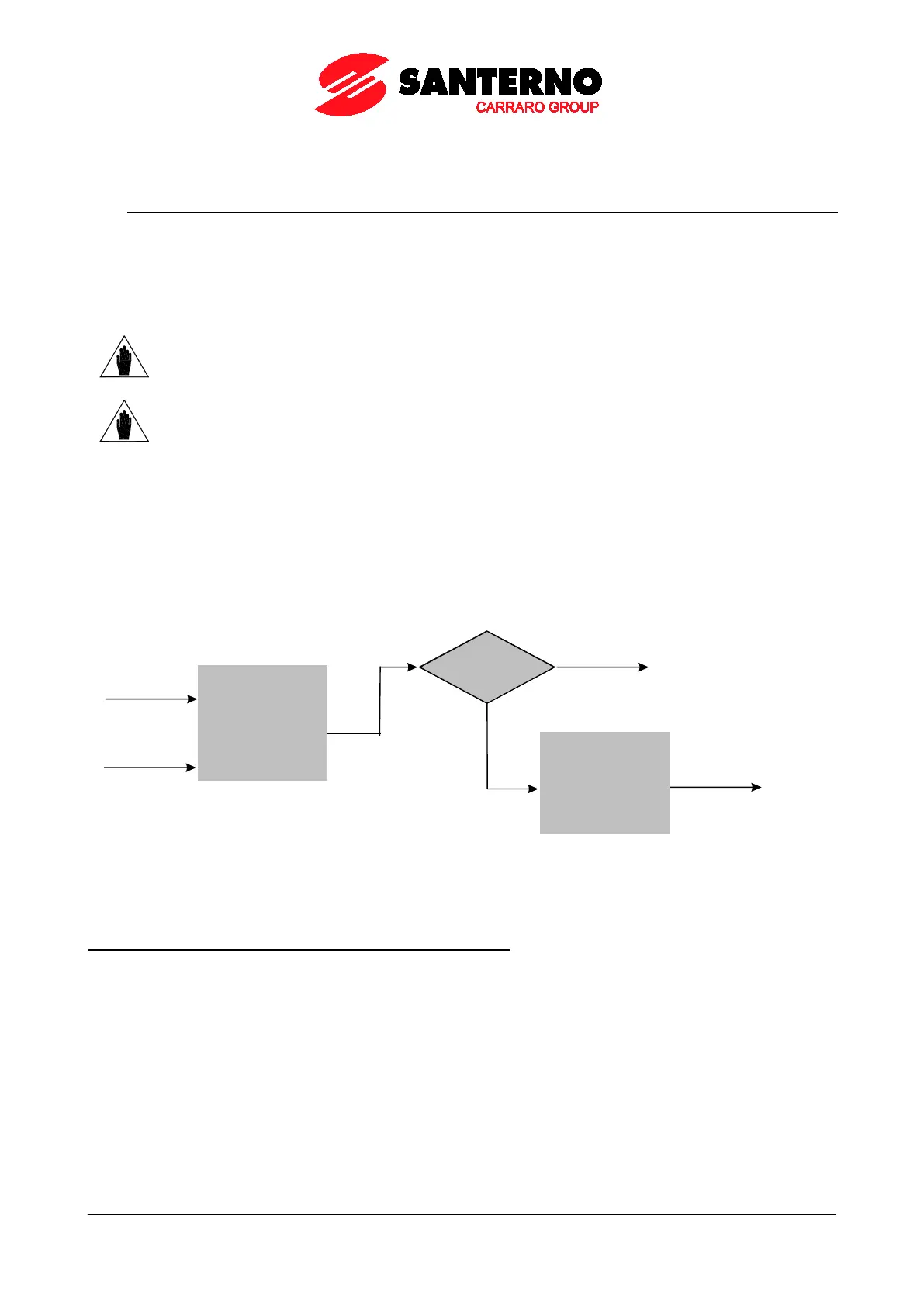
30.1.2. STRUCTURE OF THE VIRTUAL DIGITAL OUTPUTS
A virtual digital output is composed of two logic blocks allowing data processing before actuating the actual digital
output. Block 2 depends on the settings in parameters P357a (P366a, P375a, P384a).
Logic Block
set b y
parameters
P351-P357
IN PUT A
IN PUT B
f(A, B)
P357a = 0
yes
Output= f(A, B)
NO
Logic block
set by P357b
tha t tests f(A,B)
and signal C
Output=
g [f(A,B), C ]
P000658-b
Figure 39: Block diagram of the virtual digital outputs (MPL)
Operating modes set in MPL1 (2, 3, 4): P350, (P359, P368, P377)
The user can select one of the following operating modes: