SINUS PENTA
PROGRAMMING GUIDE
354/486
38.2. List of Parameters C189 to C199
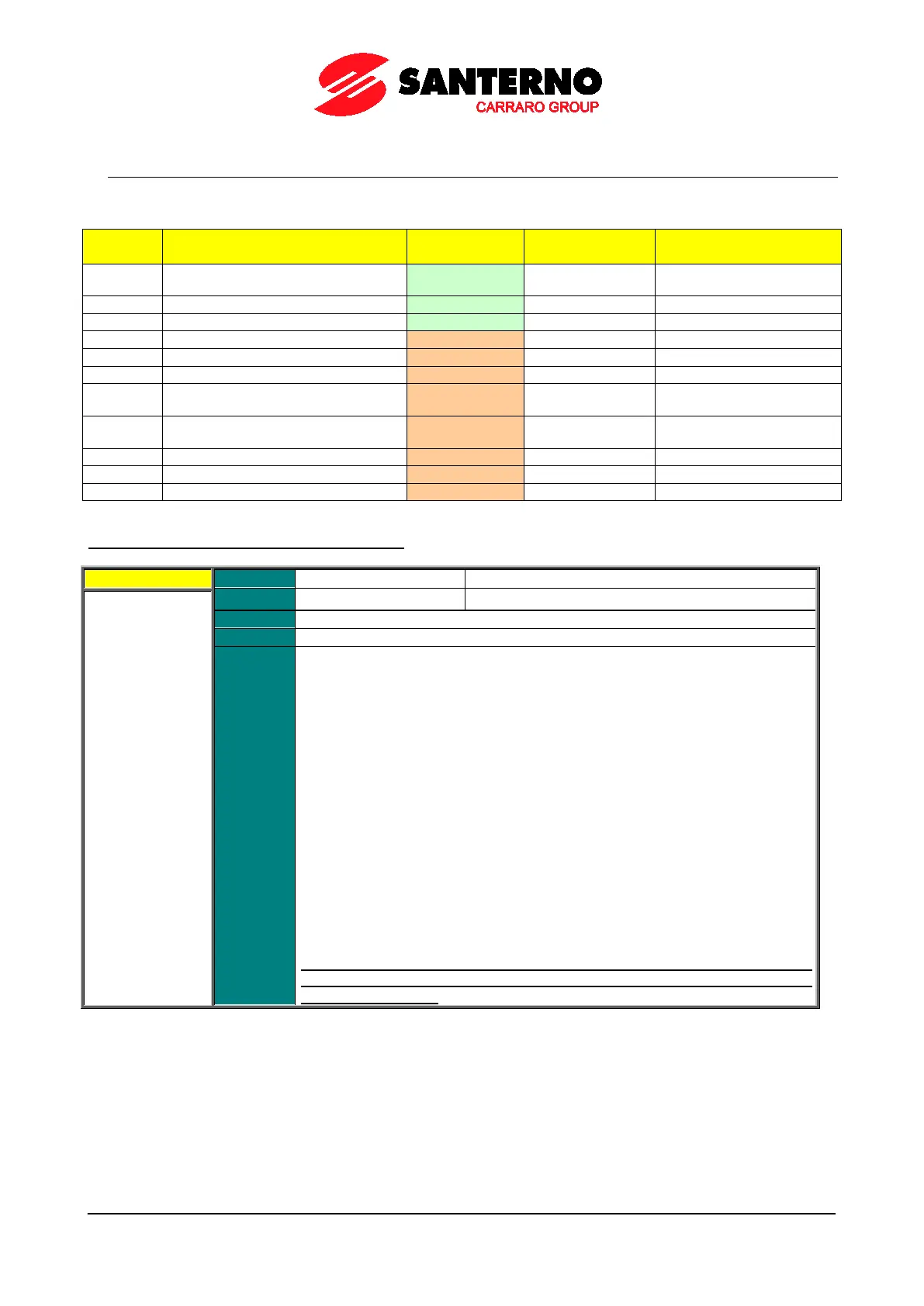
Table 110: List of parameters C189 to C199
Parameter FUNCTION User Level
DEFAULT VALUES
C189
Encoder/Frequency input operating
mode
BASIC 1189
Number of pls/rev for encoder A
Number of pls/rev for encoder B
Speed searching error timeout
Error between reference and speed
Tracking error alarm enable
C195
Filter time constant over value of
feedback from encoder
ENGINEERING 1195 5.0 ms
C196
Filter time constant over value of
reference from encoder
ENGINEERING 1196 5.0 ms
Number of channels of Encoder A
Number of channels of Encoder B
C189 Encoder/Frequency Input Operating Mode
Function
This parameter determines the operating mode of the fast acquisition digital inputs
or the encoders connected to the optional boards
. If MDI8 is used as a frequency
input, the optional
board for encoder B is not required. MDI6 digital input may be
used as a frequency input; if used along with MDI7, it can be used for encoder A
reading.
Reading both encoders A and B can be programmed; parameter C189
defines the
encoder to be used as a reference source (if set as a speed/torque reference
source in the MOTOR CONFIGURATION MENU or as a PID refer
the PID CONFIGURATION MENU
) and the encoder to be used as a speed
feedback.
Configuration allowed for quick acquisition digital inputs is shown in Table 111.
If the encoder is used as a reference source, the detected speed value will
be saturated and scaled based on values set in P073 and P074 respectively
(minimum and maximum value for the encoder).
Example:
C189 [A Reference; B Unused], P073 [–1500rpm], P074
[1500rpm] if the encoder
is used as a PID reference, the reference measure is expressed as a percentage
of the max. value [|P073|; |P074|].
If a frequency input is selected, its readout is saturated and scaled based on
parameters P071 and P072 respecti
vely (minimum and maximum value for
the frequency input).