SINUS PENTA
PROGRAMMING GUIDE
266/486
34.1.4. V/F PATTERN (IFD ONLY)
This group of parameters which is included in the Motor Control Menu defines the V/f pattern trend of the drive when it
is used as an IFD control algorithm. When setting the type of V/f pattern (e.g. C013 for motor 1), the following curves
can be used:
• Constant torque
• Quadratic
• Free setting
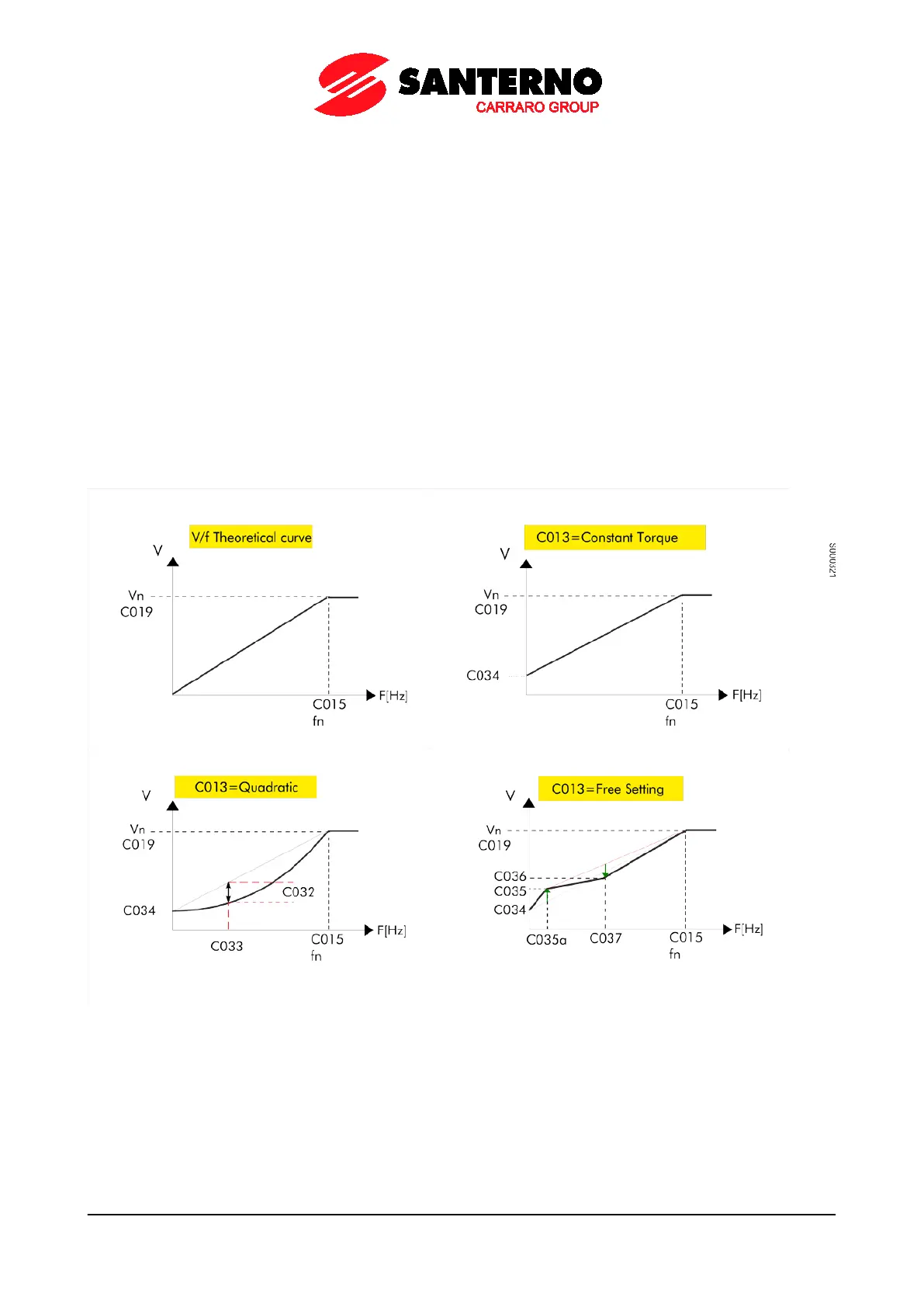
The diagram below illustrates three types of programmable curves compared to the theoretical V/f curve.
If C013 = Constant Torque, Preboost parameter C034 allows changing the starting voltage value if compared to the
theoretical V/f curve (this allows torque compensation for losses caused by the stator impedance and a greater torque at
lower revs).
If C013 = Quadratic, the drive will follow a V/f pattern with a parabolic trend. You can set the starting voltage value
(C034), the desired voltage drop if compared to the relevant constant torque (use C032) and the frequency allowing
implementing this torque reduction (use C033).
If C013 = Free Setting, you can program the starting voltage (C034 Preboost), the increase in voltage to 1/20 of the
rated frequency (C035 Boost0), and the increase in voltage (C036 Boost1) at programmable frequency (C037
Frequency for Boost1).
Figure 43: Types of programmable V/f curves
The voltage produced by the drive may be changed also by setting the Automatic increase in torque curve parameter
(C038 for motor 1).
For the description of the parameters used in the figure above, see table below.